OWNER'S MANUAL COURAGE SV470-SV620 VERTICAL CRANKSHAFT
Safety Precautions To ensure safe operation please read the following statements and understand their meaning. Also refer to your equipment owner's manual for other important safety information. This manual contains safety precautions which are explained below. Please read carefully. WARNING Warning is used to indicate the presence of a hazard that can cause severe personal injury, death, or substantial property damage if the warning is ignored.
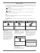
Safety Precautions (Cont.) WARNING Accidental Starts can cause severe injury or death. Disconnect and ground spark plug lead before servicing. Accidental Starts! Disabling engine. Accidental starting can cause severe injury or death. Before working on the engine or equipment, disable the engine as follows: 1) Disconnect the spark plug lead(s). 2) Disconnect negative (-) battery cable from battery. WARNING Carbon Monoxide can cause severe nausea, fainting or death.
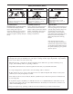
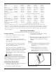
Blower Housing Blower Housing Oil Fill/Dipstick Main Control Bracket Carburetor Oil Filter Electric Starter Air Cleaner Engine Identification Label Oil Drain Plug Figure 1. Typical COURAGE® Series Vertical Shaft Engine. Use high quality detergent oil of API (American Petroleum Institute) service class SG, SH, SJ or higher. Select the viscosity based on the air temperature at the time of operation as shown in the following table.
Fuel Type For best results use only clean, fresh, unleaded gasoline with a pump sticker octane rating of 87 or higher. In countries using the Research method, it should be 90 octane minimum. Unleaded gasoline is recommended as it leaves less combustion chamber deposits. Leaded gasoline may be used in areas where unleaded is not available and exhaust emissions are not regulated. Be aware however, that the cylinder heads may require more frequent service. IMPORTANT ENGINE INFORMATION THIS ENGINE MEETS U.S.
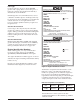
Specifications Model: ............................................................. SV470 ................ SV480 ................ SV530 ................ SV540 Bore: ................................. mm (in.) ............. 94 (3.7) ............... 94 (3.7) ............... 94 (3.7) ............... 94 (3.7) Stroke: ............................. mm (in.) ............. 86 (3.4) ............... 86 (3.4) ............... 86 (3.4) ............... 86 (3.4) Displacement: .............. cc (cu. in.) .............
2. Make sure the equipment is in neutral. 3. Activate the starter switch. Release the switch as soon as the engine starts. b. For engines equipped with a shutdown solenoid: Position the throttle control between half and full throttle; then stop the engine. NOTE: Do not crank the engine continuously for more than 10 seconds at a time. If the engine does not start, allow a 60 second cool down period between starting attempts. Failure to follow these guidelines can burn out the starter motor.
Maintenance Instructions Maintenance, repair, or replacement of the emission control devices and systems, which are being done at the customers expense, may be performed by any non-road engine repair establishment or individual. Warranty repairs must be performed by an authorized Kohler service outlet. WARNING: Accidental Starts! Disabling engine. Accidental starting can cause severe injury or death.
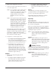
2. Remove the oil drain plug and oil fill cap/dipstick. Be sure to allow ample time for complete drainage. “F” Mark Operating Range 3. Remove the old filter and wipe off the mounting pad. 4. Reinstall the drain plug. Make sure it is tightened to 14 N·m (125 in. lb.) torque. Figure 7. Oil Level Dipstick. 5. If the level is low, add oil of the proper type, up to the “F” mark on the dipstick. (Refer to Oil Type on page 4.) Always check the level with the dipstick before adding more oil.
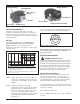
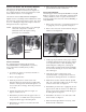
Service Precleaner and Air Cleaner Element This engine is equipped with a replaceable, high density paper air cleaner element. Some engines are also equipped with an oiled, foam precleaner, located in the outer air cleaner cover. See Figure 9. Check the air cleaner daily or before starting the engine. Check for a buildup of dirt and debris around the air cleaner system. Keep this area clean. Also check for loose or damaged components. Replace all bent or damaged air cleaner components.
Due to the deep recess around the spark plug, blowing out the cavity with compressed air is usually the most effective method for cleaning. The spark plug is most accessible when the blower housing is removed for cleaning. 2. Remove the plug and check its condition. Replace the plug if worn or reuse is questionable. Figure 11. Installing Air Cleaner Element.
Fuel Filter Some engines are equipped with an in-line fuel filter. Periodically inspect the filter and replace when dirty. Replacement is recommended annually or every 100 hours. Use a genuine Kohler filter. The carburetor is designed to deliver the correct fuelto-air mixture to the engine under all operating conditions. The main fuel jet is calibrated at the factory and is not adjustable. The low idle fuel adjusting needle is also set at the factory and normally does not need adjustment.
2. Low Idle Fuel Needle Setting: Place the throttle into the idle or slow position. 3. Low Idle Speed Setting: Place the throttle control into the idle or slow position. Set the low idle speed to 1500 RPM* (± 75 RPM) by turning the low idle speed adjusting screw in or out. Check the speed using a tachometer. Turn the low idle fuel adjusting needle out (counterclockwise) from the preliminary setting until engine speed decreases (rich). Note the position of the needle.
Parts Ordering Major Repair The engine Model, Specification, and Serial Numbers are required when ordering replacement parts from your Kohler Engine Service Dealer. These numbers are found on the identification plate which is affixed to the engine shrouding. Include letter suffixes if there are any. See Engine Identification Numbers on page 5. Major repair information is available in Kohler Engine Service Manuals.
KOHLER CO. FEDERAL AND CALIFORNIA EMISSION CONTROL SYSTEMS LIMITED WARRANTY SMALL OFF-ROAD ENGINES The U.S. Environmental Protection Agency (EPA), the California Air Resources Board (CARB), and Kohler Co. are pleased to explain the Federal and California Emission Control Systems Warranty on your small off-road equipment engine. In California beginning in 2006, "emissions" means both exhaust and evaporative emissions.
Listed below are the parts covered by the Federal and California Emission Control Systems Warranty. Some parts listed below may require scheduled maintenance and are warranted up to the first scheduled replacement point for that part.