XT-6, XTR-6, XT6.5, XT650, XT6.75, XT675, XT-7, XTR-7, XT775, XT8 Service Manual IMPORTANT: Read all safety precautions and instructions carefully before operating equipment. Refer to operating instruction of equipment that this engine powers. Ensure engine is stopped and level before performing any maintenance or service.
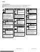
Safety SAFETY PRECAUTIONS WARNING: A hazard that could result in death, serious injury, or substantial property damage. CAUTION: A hazard that could result in minor personal injury or property damage. NOTE: is used to notify people of important installation, operation, or maintenance information. WARNING Explosive Fuel can cause fires and severe burns. Do not fill fuel tank while engine is hot or running. Gasoline is extremely flammable and its vapors can explode if ignited.
Maintenance MAINTENANCE INSTRUCTIONS WARNING Accidental Starts can cause severe injury or death. Disconnect and ground spark plug lead(s) before servicing. Before working on engine or equipment, disable engine as follows: 1) Disconnect spark plug lead(s). 2) Disconnect negative (–) battery cable from battery.
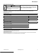
Maintenance OIL RECOMMENDATIONS We recommend use of Kohler oils for best performance. Other high-quality detergent oils (including synthetic) of API (American Petroleum Institute) service class SJ or higher are acceptable. Select viscosity based on air temperature at time of operation as shown in table below. STORAGE If engine will be out of service for 2 months or more follow procedure below. 1. Add Kohler PRO Series fuel treatment or equivalent to fuel tank.
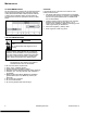
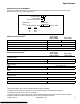
Specifications ENGINE IDENTIFICATION NUMBERS Kohler engine identification numbers (model, specification and serial) should be referenced for efficient repair, ordering correct parts, and engine replacement. Model. . . . . . . . . . . . . . . . . . . . . XT-6 Courage Engine Vertical Shaft Numerical Designation Specification . . . . . . . . . . . . . . . XT149-0001 Serial. . . . . . . . . . . . . . . . . . . . .
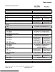
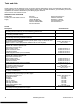
Specifications TORQUE SPECIFICATIONS3,5 XT-6, XTR-6 XT6.5, XT650, XT6.75, XT675 Connecting Rod Cap Fastener (torque in increments) XT-7, XTR-7, XT775, XT8 12.5 N·m (110 in. lb.) Crankcase Oil Drain Plug7 Oil Pan Screw 13.6 N·m (120 in. lb.) 11.0 N·m (98 in. lb.) 14.7 N·m (130 in. lb.) Cylinder Head Fastener (torque in 2 increments) first to 14 N·m (123 in. lb.) finally to 27.8 N·m (246 in. lb.) Flywheel Retaining Nut 51.5 N·m (38 ft. lb.
Specifications CLEARANCE SPECIFICATIONS3 XT-6, XTR-6 XT6.5, XT650, XT6.75, XT675 Camshaft End Play Running Clearance 0.3/0.85 mm (0.0118/0.0335 in.) 0.013/0.0555 mm (0.00051/0.00217 in.) Connecting Rod Connecting Rod-to-Crankpin Running Clearance New Connecting Rod-to-Crankpin Side Clearance New Connecting Rod-to-Piston Pin Running Clearance Piston Pin End I.D. New @ 21°C (70°F) 0.025/0.045 mm (0.0009/0.0017 in.) 0.03/0.48 mm 0.13/0.58 mm (0.00118/0.0189 in.) (0.0051/0.0228 in.) 0.008/0.025 mm (0.
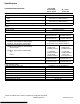
Specifications CLEARANCE SPECIFICATIONS3 XT-6, XTR-6 XT6.5, XT650, XT6.75, XT675 Governor Governor Cross Shaft -to-Crankcase Running Clearance Cross Shaft O.D. New Gear Shaft O.D. New Governor Gear Shaft-to-Governor Gear Running Clearance 0.020/0.064 mm (0.0007/0.0025 in.) 5.96/5.98 mm (0.2346/0.2354 in.) 6.01/6.03 mm (0.2366/0.2374 in.) 0.09/0.19 mm (0.0035/0.0074 in.) Ignition Spark Plug Gap Module Air Gap 0.76 mm (0.030 in.) 0.254 mm (0.010 in.) Piston, Piston Rings, and Piston Pin Pin Bore I.
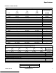
Specifications GENERAL TORQUE VALUES English Fastener Torque Recommendations for Standard Applications Bolts, Screws, Nuts and Fasteners Assembled Into Cast Iron or Steel Grade 2 or 5 Fasteners Into Aluminum Size Grade 2 Tightening Torque: N·m (in. lb.) ± 20% 8-32 2.3 (20) 10-24 3.6 (32) 10-32 3.6 (32) 1/4-20 7.9 (70) 1/4-28 9.6 (85) 5/16-18 17.0 (150) 5/16-24 18.7 (165) 3/8-16 29.4 (260) 3/8-24 33.9 (300) Grade 5 Grade 8 2.8 (25) 4.5 (40) 4.5 (40) 13.0 (115) 15.8 (140) 28.3 (250) 30.
Tools and Aids Certain quality tools are designed to help you perform specific disassembly, repair, and reassembly procedures. By using these tools, you can properly service engines easier, faster, and safer! In addition, you’ll increase your service capabilities and customer satisfaction by decreasing engine downtime. Here is a list of tools and their source. SEPARATE TOOL SUPPLIERS Kohler Tools Contact your local Kohler source of supply. SE Tools 415 Howard St.
Tools and Aids TOOLS Description Hydraulic Valve Lifter Tool For removing and installing hydraulic lifters. Ignition System Tester For testing output on all systems, including CD. Inductive Tachometer (Digital) For checking operating speed (RPM) of an engine. Offset Wrench (K and M Series) For removing and reinstalling cylinder barrel retaining nuts. Oil Pressure Test Kit For testing/verifying oil pressure on pressure lubricated engines.
Tools and Aids FLYWHEEL HOLDING TOOL ROCKER ARM/CRANKSHAFT TOOL A flywheel holding tool can be made out of an old junk flywheel ring gear and used in place of a strap wrench. 1. Using an abrasive cut-off wheel, cut out a six tooth segment of ring gear as shown. 2. Grind off any burrs or sharp edges. 3. Invert segment and place it between ignition bosses on crankcase so tool teeth engage flywheel ring gear teeth.
Troubleshooting TROUBLESHOOTING GUIDE When troubles occur, be sure to check simple causes which, at first, may seem too obvious to be considered. For example, a starting problem could be caused by an empty fuel tank. Some general common causes of engine troubles are listed below and vary by engine specification. Use these to locate causing factors. Engine Cranks But Will Not Start ● Battery connected backwards. ● Blown fuse. ● Carburetor solenoid malfunction. ● Choke not closing.
Troubleshooting Engine Loses Power ● Dirty air cleaner element. ● Engine overheated. ● Excessive engine load. ● Restricted exhaust. ● Faulty spark plug(s). ● High crankcase oil level. ● Incorrect governor setting. ● Low battery. ● Low compression. ● Low crankcase oil level. ● Quality of fuel (dirt, water, stale, mixture). Engine Uses Excessive Amount of Oil ● Loose or improperly torqued fasteners. ● Blown head gasket/overheated. ● Breather reed broken.
Troubleshooting CRANKCASE VACUUM TEST WARNING WARNING Carbon Monoxide can cause severe nausea, fainting or death. Avoid inhaling exhaust fumes. Engine exhaust gases contain poisonous carbon monoxide. Carbon monoxide is odorless, colorless, and can cause death if inhaled. Rotating Parts can cause severe injury. Stay away while engine is in operation. Keep hands, feet, hair, and clothing away from all moving parts to prevent injury. Never operate engine with covers, shrouds, or guards removed.
Troubleshooting COMPRESSION TEST For Command Twins: A compression test is best performed on a warm engine. Clean any dirt or debris away from base of spark plug(s) before removing them. Be sure choke is off, and throttle is wide open during test. Compression should be at least 160 psi and should not vary more than 15% between cylinders. All other models: These engines are equipped with an automatic compression release (ACR) mechanism.
Air Cleaner/Intake AIR CLEANER These systems are CARB/EPA certified and components should not be altered or modified in any way. Air Cleaner Components D C E A D C B F Precleaner (if equipped) 1. Remove precleaner. 2. Replace or wash precleaner in warm water with detergent. Rinse and allow to air dry. 3. Reinstall precleaner into cover, aligning hole in precleaner with upper cover knob. Paper Element 1. Remove paper element from base and replace. 2.
Fuel System Typical carbureted fuel system and related components include: ● Fuel tank. ● Fuel line. ● In-line fuel filter. ● Fuel tank filter (in-nipple). ● Fuel shut-off valve (if equipped). ● Carburetor. Fuel tank outlet is located above carburetor inlet, allowing gravity to feed fuel through in-line filter and fuel line to carburetor. Fuel enters carburetor through fuel shut-off valve and sediment bowl and then goes to carburetor float bowl. Fuel is drawn into carburetor body and mixed with air.
Fuel System CARBURETOR WARNING Explosive Fuel can cause fires and severe burns. Do not fill fuel tank while engine is hot or running. Typical One-Barrel Carburetor Components These engines are equipped with a fixed main jet carburetor. Carburetor is designed to deliver correct fuelto-air mixture to engine under all operating conditions. Idle mixture is set at factory and cannot be adjusted.
Fuel System Troubleshooting-Carburetor Related Causes Condition Engine starts hard, runs rough, or stalls at idle speed. Engine runs rich (indicated by black, sooty exhaust smoke, misfiring, loss of speed and power, governor hunting, or excessive throttle opening). Possible Cause Low idle fuel mixture (some models)/ speed improperly adjusted. Clogged air cleaner. Choke partially closed during operation. Dirt under fuel inlet needle. Conclusion Adjust idle speed screw or clean carburetor.
Fuel System ● Inspect carburetor body for cracks, holes, and other wear or damage. ● Inspect float for cracks, holes, and missing or damaged float tabs. Check float hinge and shaft for wear or damage. ● Inspect fuel inlet needle and seat for wear or damage. 1. Perform removal procedures for appropriate air cleaner and carburetor outlined in Disassembly. 2. Clean exterior surfaces of dirt or foreign material before disassembling carburetor.
Fuel System 3. Remove vacuum hose from carburetor vacuum fitting. Attach a vacuum gauge or manometer to carburetor vacuum fitting. Run engine while holding choke plate open. Gauge should indicate a vacuum with a minimum of 15" of water. If reading is correct, check again for binding of restricted linkage. 4. If vacuum indicated is less than 15" of water, problem is not an auto choke issue.
Fuel System Auto Choke Components - Link Design B A E D C B When engine is cold, spring around base of choke shaft holds choke closed for starting. When engine starts, governor closes throttle from wide open to set governor speed. As throttle closes, link between throttle and choke operates choke to a slightly open position. After engine warms up, bimetallic spring overcomes choke shaft spring force and holds choke completely open. Use these steps to check function of link design auto choke. 1.
Governor System GOVERNOR Governor Components B C A G K F E D H J I A Control Spring B Intermediate Control Lever C Control Bracket D Governor Lever E Compression Spring F Linkage G Regulating Pin H Flyweight(s) I Governor Gear J Governor Gear Shaft K Governor Shaft Retainer Governed speed setting is determined by position of throttle control. It can be variable or constant, depending on engine application.
Governor System ● When load is applied and engine speed and governor gear speed decreases, governor spring tension moves governor arm to open throttle plate wider. This allows more fuel into engine, increasing engine speed. As speed reaches governed setting, governor spring tension and force applied by regulating pin will again offset each other to hold a steady engine speed. Initial Governor Adjustment Make this initial adjustment whenever governor arm is loosened or removed from cross shaft.
Lubrication System These engines use a splash lubrication system, supplying necessary lubrication to crankshaft, camshaft, connecting rod, and valve train components. Lubrication Components C A B D A 1/4 Turn Cap B Threaded Cap OIL RECOMMENDATIONS Refer to Maintenance. CHECK OIL LEVEL NOTE: To prevent extensive engine wear or damage, never run engine with oil level below or above operating range indicator on dipstick. Ensure engine is cool. Clean oil fill cap/dipstick areas of any debris. 1.
Electrical System SPARK PLUGS CAUTION Electrical Shock can cause injury. Do not touch wires while engine is running. Spark Plug Component and Details Inspection Inspect each spark plug as it is removed from cylinder head. Deposits on tip are an indication of general condition of piston rings, valves, and carburetor. Normal and fouled plugs are shown in following photos: Normal A B Plug taken from an engine operating under normal conditions will have light tan or gray colored deposits.
Electrical System Carbon Fouled Soft, sooty, black deposits indicate incomplete combustion caused by a restricted air cleaner, over rich carburetion, weak ignition, or poor compression. Overheated Chalky, white deposits indicate very high combustion temperatures. This condition is usually accompanied by excessive gap erosion. Lean carburetor settings, an intake air leak, or incorrect spark timing are normal causes for high combustion temperatures. 28 KohlerEngines.com 14 690 01 Rev.
Electrical System ELECTRONIC IGNITION SYSTEM These engines are equipped with dependable solid-state magneto ignition systems. Two types of ignition modules are used on these engines, capacitive discharge ignition (CDI), and inductive discharge ignition (IDI). Both ignition systems are designed to be trouble free for life of engine. Other than periodically checking/replacing spark plugs, no maintenance or timing adjustments are necessary or possible. Mechanical systems do occasionally fail or break down.
Electrical System Electronic Ignition Systems Tests Test Ignition System 1. Make sure spark plug lead is connected to spark plug. 2. Check condition of spark plug. Make sure gap is set to 0.76 mm (0.030 in.). Condition Spark plug is not receiving ignition pulse. Spark plug in bad condition. Possible Cause Spark Plug Spark Plug Conclusion Check gap and adjust if necessary; reinstall plug. Replace plug, set gap, and install.
Starter System NOTE: Do not crank engine continuously for more than 10 seconds. Allow a 60 second cool down period between starting attempts. Failure to follow these guidelines can burn out starter motor. NOTE: If engine develops sufficient speed to disengage starter but does not keep running (a false start), engine rotation must be allowed to come to a complete stop before attempting to restart engine.
Starter System Remove Starter NOTE: Whenever possible, an impact wrench should be used to loosen nuts securing retractable starter. 1. Remove nuts securing starter to blower housing. 2. Remove starter assembly. Rope Replacement NOTE: Do not allow pulley/spring to unwind. Enlist aid of a helper if necessary. Rope can be replaced without complete starter disassembly. 1. Remove starter assembly from engine. 2. Pull rope out approximately 12 in.
Disassembly/Inspection and Service WARNING Accidental Starts can cause severe injury or death. Disconnect and ground spark plug lead(s) before servicing. Before working on engine or equipment, disable engine as follows: 1) Disconnect spark plug lead(s). 2) Disconnect negative (–) battery cable from battery.
Disassembly/Inspection and Service Clean all parts thoroughly as engine is disassembled. Only clean parts can be accurately inspected and gauged for wear or damage. There are many commercially available cleaners that will quickly remove grease, oil, and grime from engine parts. When such a cleaner is used, follow manufacturer's instructions and safety precautions carefully. Make sure all traces of cleaner are removed before engine is reassembled and placed into operation.
Disassembly/Inspection and Service Remove Retractable Starter Remove screws securing retractable starter assembly to engine. Carburetor Components Remove Carburetor with Primer or Carburetor with Choke (if equipped) Remove Blower Housing Lift off blower housing and retain stud spacers. Remove Muffler Assembly 1. Remove nuts securing muffler guard to cylinder head. 2. Slide muffler off studs. 3. Remove heat deflector gasket from exhaust studs, noting orientation. Remove Air Cleaner Assembly 1.
Disassembly/Inspection and Service Remove Carburetor with Auto Choke (if equipped) B E C D F A 1. Remove screws securing arm assembly to carburetor. 2. Disconnect fuel line. 3. Remove wire choke linkage while sliding carburetor away from engine a couple of inches. 4. Disconnect governor linkage and linkage spring from carburetor. 5. Remove carburetor. 6. Remove nuts securing arm assembly to muffler. Second nut is located behind arm assembly base securing it to top of muffler. 7.
Disassembly/Inspection and Service Remove Governor Lever Loosen governor lever nut and slide lever off governor shaft. Flywheel/Ignition/Fuel Tank Components F Remove Ignition Module 1. Disconnect kill lead from ignition module. 2. Remove screw and stud securing ignition module. Mark stud for identification during reassembly. G H Disconnect Flywheel Brake Spring Grasp 1 end of flywheel brake spring with a pliers and stretch it to disconnect it. E D I J C K B Remove Flywheel 1.
Disassembly/Inspection and Service Cylinder Head Components P M L O K N I F J C G H E D B A A A Valve Cover B Gasket C Jam Nut D Rocker Arm Pivot E Rocker Arms F Rocker Arm Stud G Push Rod H Push Rod Guide Plate I Valve Keeper J Valve Spring K Intake Valve Seal L Spark Plug M Baffle N Cylinder Head O Valve P Dowel Pin Remove Valve Cover Valve Cover with Gasket 1. Remove screws from valve cover. 2. Remove cover and gasket.
Disassembly/Inspection and Service Remove Rocker Arms Noting orientation, lift rocker arms off rocker studs. Remove Push Rods Remove push rods and mark them for reinstallation. Remove Rocker Studs Unscrew and remove rocker studs from cylinder head. Remove Guide Plate 1. Remove guide plate from rocker studs. 2. Note orientation of guide plate (tabs down) for use during reassembly. Remove Cylinder Head 1. Remove screws securing cylinder head. 2. Remove cylinder head, noting positioning of dowels. 3.
Disassembly/Inspection and Service Remove Valve Assembly NOTE: Only intake valve has a seal. There is no valve seal on exhaust side. 1. Push down on valve spring keepers to release valve springs from valve stems. 2. Remove valve spring keepers and springs. 3. Push end of intake valve to release valve seal. 4. Remove both valves from opposite side of head. Inspection and Service Hard starting, or loss of power accompanied by high fuel consumption, may be symptoms of faulty valves.
Disassembly/Inspection and Service Crankcase Components A A B C B C D E G H F F I H I M L J K G P N M L K Q N R P J R O O U Q S S T V T A Crankcase Oil Seal B Crankcase C Governor Cross Shaft D Oil Pan Gasket E Crankcase Bearing F Camshaft G Piston Pin Retainer H Piston Pin I Piston J Piston Ring Set K Connecting Rod L Connecting Rod End Cap M Crankshaft N Retainer O Governor Shaft P Governor Gear Q Governor Washer R Governor Cup S Oil Pan T
Disassembly/Inspection and Service Remove Camshaft Remove camshaft from crankcase. Inspection and Service Inspect gear teeth of camshaft. If teeth are badly worn or chipped, or if some are missing, replacement of camshaft will be necessary. If unusual wear or damage is evident on either camshaft lobes or mating tappets camshaft and both tappets must be replaced. Check condition and operation of Automatic Compression Release (ACR) mechanism. ACR These engines are equipped with an ACR mechanism.
Disassembly/Inspection and Service Some important points to remember when servicing piston rings: 1. Cylinder bore must be de-glazed before service ring sets are used. 2. If cylinder bore does not need re-boring and if old piston is within wear limits and free of score or scuff marks, old piston may be reused. 3. Remove old rings and clean up grooves. Never reuse old rings. 4. Before installing new rings on piston, place top 2 rings, each in turn, in its running area in cylinder bore and check end gap.
Disassembly/Inspection and Service Remove Crankshaft Remove crankshaft. Inspection and Service Inspect gear teeth of crankshaft and ACR gear. If any teeth are badly worn or chipped, or if some are missing, replacement of crankshaft will be necessary. Inspect crankshaft bearing surfaces for scoring, grooving, etc. Measure running clearance between crankshaft journals and their respective bearing bores.
Reassembly Crankcase Components A A B C B C D E G H F F I H I M L J K G P N M L K Q N R P J R O O U Q S S T V T A Crankcase Oil Seal B Crankcase C Governor Cross Shaft D Oil Pan Gasket E Crankcase Bearing F Camshaft G Piston Pin Retainer H Piston Pin I Piston J Piston Ring Set K Connecting Rod L Connecting Rod End Cap M Crankshaft N Retainer O Governor Shaft P Governor Gear Q Governor Washer R Governor Cup S Oil Pan T Oil Pan Oil Seal U Dips
Reassembly Install Piston and Connecting Rod NOTE: Proper orientation of piston and connecting rod inside engine is extremely important. Improper orientation can cause extensive wear or damage. 1. Stagger piston rings in grooves until end gaps are 60° or more apart. Lubricate cylinder bore, crankshaft journal, connecting rod journal, piston, and rings with engine oil. 2. Compress piston rings using a piston ring compressor. 3. Position triangle on top of piston toward push rod chamber. 4.
Reassembly 4. Guide oil pan onto crankcase, ensuring camshaft and governor gear align with their mating surfaces. Rotate crankshaft slightly to help engage governor gear. 5. Install and finger tighten screws, securing oil pan to crankcase. 6. Use torque sequence shown and torque oil pan screws to: Sealant Pattern XT775, XT8 A Model Torque XT6, XTR-6 XT6.5, XT6.75 11.0 N·m (98 in. lb.) XT650, XT675 XT-7, XTR-7 XT775, XT8 XT6.5, XT6.75 14.7 N·m (130 in. lb.) A A 1.5 mm (1/16 in.
Reassembly Cylinder Head Components P M L O K N I F J C H G E D B A A A Valve Cover B Gasket C Jam Nuts D Rocker Arm Pivot E Rocker Arms F Rocker Arm Stud G Push Rods H Push Rod Guide Plate I Valve Keeper J Valve Spring K Intake Valve Seal L Spark Plug M Baffle N Cylinder Head O Valve P Dowel Pin Install Cylinder Head Assembly Prior to assembly, lubricate all components with engine oil, including tips of valve stems and valve guides. Install Valve Train 1.
Reassembly Install Cylinder Head Torque Sequence Install Valve Cover Torque Sequence 3 2 1 4 NOTE: Do not reuse cylinder head gasket. Always replace with new gasket. 1. Examine sealing surfaces of cylinder head and crankcase for nicks or burrs. 2. Using cylinder head dowels as a guide, install a new head gasket. 3. Match sides of head together and finger tighten screws. 4. Torque screws in two stages; first to 14 N·m (123 in. lb.), finally to 27.8 N·m (246 in. lb.), following sequence shown.
Reassembly Install New Spark Plug Flywheel/Ignition/Fuel Tank Components 1. Set gap of a new spark plug to 0.76 mm (0.03 in.). 2. Install spark plug and torque to 27 N·m (20 ft. lb.). G Install Flywheel Brake Assembly Dipstick Side of Engine 1. Install spacers onto brake assembly screws. Fuel Cap Side of Engine 1. Place brake assembly onto engine and loosely install 2 brake assembly screws. 2. Install a caliper between brake lever and bracket to establish a 50 mm (1.968 in.
Reassembly Install Flywheel CAUTION Damaging Crankshaft and Flywheel can cause personal injury. Using improper procedures can lead to broken fragments. Broken fragments could be thrown from engine. Always observe and use precautions and procedures when installing flywheel. NOTE: Before installing flywheel make sure crankshaft taper and flywheel hub are clean, dry, and completely free of lubricants.
Reassembly Install Governor Assembly 1. Install governor lever onto governor shaft with lever up. 2. Attach throttle linkage and linkage spring to top of governor lever.
Reassembly Loosely attach speed control bracket to crankcase using shorter screws. Long screw will be used later for attaching air cleaner body. Auto Choke Components Install Governor Spring Install governor spring between governor lever and speed control bracket.
Reassembly Install Carburetor with Auto Choke (if equipped) 1. Mount arm assembly onto muffler securing with nuts. Torque to 8.5 N·m (75 in. lb.). 2. Slide carburetor at least halfway onto mounting studs. Connect throttle linkage and linkage spring to carburetor. 3. Connect wire choke linkage while sliding carburetor to its seated position against engine. 4. Insert screws connecting arm assembly to carburetor. Torque to 2.3 N·m (20 in. lb.).
Reassembly Install Air Cleaner Assembly 1. Attach primer hose to carburetor (if equipped). 2. Slide air cleaner gasket onto carburetor studs. 3. Slide air cleaner base onto carburetor studs. Attach base by loosely screwing nuts onto studs, and screw into crankcase. 4. Attach breather hose to crankcase. 5. Secure air cleaner base by torquing nuts and screw to 8 N·m (71 in. lb.). 6. Install paper element and foam precleaner (if equipped) into air cleaner base.
© 2014 by Kohler Co. All rights reserved. 56 KohlerEngines.com 14 690 01 Rev.