SERVICE MANUAL COURAGE XT-6, XT-7 VERTICAL CRANKSHAFT
Contents Section 1. Safety and General Information ............................................................................. Section 2. Tools and Aids ......................................................................................................... Section 3. Troubleshooting ...................................................................................................... Section 4. Air Cleaner and Air Intake System .........................................................................
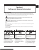
Section 1 Safety and General Information 1 Section 1 Safety and General Information Safety Precautions To ensure safe operation please read the following statements and understand their meaning. Also refer to your equipment manufacturer's manual for other important safety information. This manual contains safety precautions which are explained below. Please read carefully.
Section 1 Safety and General Information WARNING WARNING ([SORVLYH )XHO FDQ FDXVH ¿UHV DQG severe burns. Carbon Monoxide can cause severe nausea, fainting or death. ȱȱęȱȱȱȱ ȱȱ engine is hot or running. Avoid inhaling exhaust fumes, and never run the engine in a closed ȱȱęȱǯ Explosive Fuel! ȱȱ¡¢ȱĚȱȱ its vapors can explode if ignited.
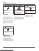
Section 1 Safety and General Information (QJLQH ,GHQWL¿FDWLRQ 1XPEHUV When ordering parts, or in any communication involving an engine, always give the Model, ęǰȱȱ ȱ of the engine. 1 ȱęȱȱȱȱȱȱ Ĝ¡ȱȱȱȱǯȱ ȱ ȱŗȬŗǯȱ ȱ ¡ȱȱȱȱȱ ȱȱ ȱŗȬŘǯ ,GHQWL¿FDWLRQ /DEHO )LJXUH ,GHQWL¿FDWLRQ /DEHO A. Model No. XT 7 Courage Vertical Shaft Engine Numerical Designation B. Spec. No.
Section 1 Safety and General Information Oil Recommendations Fuel Recommendations Using the proper type and weight of oil in the engine is extremely important, as is daily checking of oil level ȱȱȱ¢ǯȱ ȱȱȱȱȱ oil, or using dirty oil, will cause premature engine wear and failure. Oil Type Use high quality detergent oil of ȱǻ ȱ ȱ Ǽȱȱȱ ȱȱ.
Section 1 Safety and General Information Periodic Maintenance WARNING: Accidental Starts! Disabling engine. Accidental starting can cause severe injury or death. Before working on the engine or equipment, disable the engine by disconnecting the spark plug lead. Maintenance Schedule These required maintenance procedures should be performed at the frequency stated in the table. They should also be included as part of any seasonal tune-up.
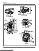
Section 1 Safety and General Information (IF EQUIPPED) (IF EQUIPPED) Dimensions in millimeters. Inch equivalents shown in parentheses. Figure 1-5. Typical Engine Dimensions. 1.
Section 1 Safety and General Information *HQHUDO 6SHFL¿FDWLRQVï 1 ȱ ȱǻȓȱřŜŖŖȱ Ǽ XT-6 ................................................................................................................. ŘǯŜȱ ȱǻřǯśȱ Ǽ XT-7 ................................................................................................................. řǯŚȱ ȱǻŚǯśȱ Ǽ ȱ ȱ ȱǻȓȱŘŜŖŖȱ Ǽ XT-6 .................................................................................................................
Section 1 Safety and General Information Connecting Rod ȱ ȱ ȱ Ŷ .................................................................. ŗŘǯśȱ ȉȱǻŗŗŖȱǯȱǯǼ Connecting Rod-to-Crankpin Running Clearance New............................................................................................................... ŖǯŖŘśȬŖǯŖŚśȱȱǻŖǯŖŖŖşȬŖǯŖŖŗŝȱǯǼ Connecting Rod-to-Crankpin Side Clearance................................................
Section 1 Safety and General Information Cylinder Bore ¢ȱ ȱ ǯ ǯ New.............................................................................................................. ŝŖǯŖŖŖȬŝŖǯŖŗśȱȱǻŘǯŝśśŞȬŘǯŝśŜŚȱǯǼ Max. Taper .................................................................................................. ŗŘǯŝȱȱǻŖǯŖŖŖśȱǯǼ Max. Out of Round ....................................................................................
Section 1 Safety and General Information 0XIÀHU Exhaust Stud Torque ........................................................................................ 9.0 N·m (80 in. lb.) ¡ȱ ȱ ȱ ȱ........................................................................ ȱşǯśȱ ȉȱǻŞŚȱǯȱǯǼ Oil ȱ ȱ ȱ Ŷ ...................................................................................... ȱŗŘǯřȱ ȉȱǻŗŖşȱǯȱǯǼ Oil Drain Plug Torque³...................................................
Section 1 Safety and General Information Valves and Valve Lifters (continued) 1 ȱ ȱ ȬȬ ȱ ȱ ȱ ............................... ŖǯŖŘŖȬŖǯŖŚŝȱȱǻŖǯŖŖŖŝȬŖǯŖŖŗŞȱǯǼ Exhaust Valve Stem-to-Valve Guide Running Clearance ............................ ŖǯŖśśȬŖǯŖŞŘȱȱǻŖǯŖŖŘŗȬŖǯŖŖřŘȱǯǼ ȱ ȱ ȱ ǯ ǯ New..............................................................................................................
Section 1 Safety and General Information General Torque Values Metric Fastener Torque Recommendations for Standard Applications Tightening Torque: N·m (in. lb.) + or - 10% Property Class Size M4ȱ M5ȱ M6ȱ M8ȱ 4.8 5.8 8.8 10.9 12.
Section 2 Tools & Aids Section 2 Tools & Aids 2 ȱ¢ȱȱȱȱȱȱȱęȱ¢ǰȱǰȱȱ¢ȱǯȱ ¢ȱ ȱȱȱȱȱǰȱȱȱȱȱȱǰȱǰȱȱǯȱ ȱǰȱȱ ȱȱȱȱ ȱȱȱ¢ȱȱȱ ǯ Here is the list of tools and their sources: Separate Tool Suppliers: Kohler Tools Contact your local Kohler ȱȱ¢ǯȱ SE Tools Śŗśȱ
Section 2 Tools & Aids 2.
Section 3 Troubleshooting Section 3 Troubleshooting 3 Troubleshooting Guide When troubles occur, be sure to check the simple ǰȱ ȱȱęȱ¢ȱȱȱȱȱȱ considered. For example, a starting problem could ȱȱ¢ȱȱ¢ȱȱǯ ȱȱ¢ȱȱȱȱȱȱ below. Use these to help locate the possible cause(s). Engine Cranks But Will Not Start ȱ ŗǯȱ ¢ȱȱǯ ȱ Řǯȱ ȱǰȱȱȱ ȱȱȱ¢ǯ ȱ řǯȱ ȱȱǯ 4.
Section 3 Troubleshooting Engine Knocks ȱ ŗǯȱ ¡ȱȱǯ ȱ Řǯȱ ȱȱȱǯ ȱ řǯȱ ȱȱȱȱ¢ǯ 4. Internal wear or damage. ȱ śǯȱ ¢ȱȱǯ ȱ Ŝǯȱ ȱȱȱǯ Engine Loses Power ȱ ŗǯȱ ȱȱȱǯ ȱ Řǯȱ ȱȱȱǯ ȱ řǯȱ ¢ȱȱȱǯ ȱ Śǯȱ ȱȱ ȱȱȱ¢ǯ ȱ śǯȱ ¡ȱȱǯ ȱ Ŝǯȱ ȱǯ ȱ ŝǯȱ ¢ȱȱǯ 8. Low compression. 9. Exhaust restriction.
Section 3 Troubleshooting Basic Engine Tests Crankcase Vacuum Test ȱȱȱȱȱȱȱȱ crankcase when the engine is operating. Pressure ȱȱȱǻ¢ȱȱ¢ȱȱȱȱ ¢ȬȱǼȱȱȱȱȱȱ ȱȱȱȱǰȱǰȱȱȱȱǯ ȱȱȱȱȱ ȱȱ ȱ ȱȱȦȱȱǯȱ ȱ Section 2, Tools and Aids.
Section 3 Troubleshooting Cylinder Leakdown Test ȱ¢ȱ ȱȱȱȱȱȱȱ ȱȱȱǯȱ ¢ȱ£ȱȱȱ ȱȱȱ¡ȱȱǰȱ¢ȱȱ ȱȱȱȱȱȱȱǰȱȱ ȱ ¢ǯ ȱ¢ȱ ȱȱȱȱ¢ȱǰȱ ¡ȱ ȱȱȱȱǯȱ ȱȱȱȱȱȱȱȱ Ĵȱȱȱȱȱȱȱǯ Leakdown Test Instructions ȱ ŗǯȱ ȱȱ
Section 4 Air Cleaner and Air Intake System Section 4 Air Cleaner and Air Intake System Air Cleaner This engine is equipped with a replaceable, high density paper air cleaner. An optional foam precleaner may also be included. See Figure 4-1. Intake air is drawn in through the blower housing, and passes through the precleaner (if equipped), the paper element and then into the carburetor. The outer air cleaner cover is secured by one knob, and removed by turning the knob counterclockwise.
Section 4 Air Cleaner and Air Intake System Service Paper Element Check the paper element for dirty, loose or damaged parts every 25 hoursȱȱDzȱȱĞȱȱ extremely dusty or dirty conditions. Yearly or every 100 hours of operation replace the paper element. Follow these instructions to service: 1. Loosen the air cleaner knob and remove the cover. Remove the paper air cleaner element and the precleaner (if equipped). See Figure 4-1. 2.
Section 4 Air Cleaner and Air Intake System NOTE: Before reinstalling an air cleaner base that has been removed, make sure the metal bushings in the base mounting holes are present. The bushings prevent damage to the base and help maintain the proper mounting torque. Reassembly The following procedure outlines complete reassembly of all air cleaner components. 1. Reconnect the primer bulb hose (if equipped). See Figure 4-3.
Section 4 Air Cleaner and Air Intake System 4.
Section 5 Fuel System and Governor Section 5 Fuel System and Governor Fuel Recommendations WARNING: Explosive Fuel! ȱȱ¡¢ȱĚȱȱȱȱȱ¡ȱ ȱǯȱ ȱȱ¢ȱȱȱǰȱȱ Ȭǰȱȱǰȱ ¢ȱȱȱ ȱĚǯȱ ȱȱęȱȱȱȱ ȱȱȱȱȱ ȱǰȱȱȱȱȱȱȱȱȱȱ ȱ ȱȱȱȱȱȱǯȱ ȱȱ ȱȱȱȱȱǯȱ ȱ
Section 5 Fuel System and Governor Fuel System Test Guide Test Conclusion ŗǯȱȱ ȱȱȱ DZ ȱ ǯȱ ȱȱȱȱǰȱȱȱȱǯ ȱ ǯȱ ȱȱȱȱȱȱǯ 1. Řǯȱȱ ȱ ǯȱ ȱ ǯȱ c. ȱ ǯȱ ȱȱȱȱȱǯ ȱȱȱȱȱǯ ȱȱȱǻȱǼǯ Turn engine over several times. ȱȱȱȱȱȱȱȱǯ Řǯȱȱ ȱȱȱȱȱȱȱȱǰȱȱȱȱ the combustion chamber.
Section 5 Fuel System and Governor Fuel System Troubleshooting Guide 1. Engine starts hard, runs rough or stalls at idle. 1. Engine is out of fuel. ȱ ȱ ȱęȱȱDzȱȱȱǯ ȱ ȱ ȱȱȱ¢Dzȱȱȱȱȱǯ Řǯȱȱ ȱȱȱǻȱ¢ȱȱ¢ȱ ǰȱęǰȱȱȱȱȱ ǰȱȱ governor hunting).
Section 5 Fuel System and Governor Carburetor Removal NOTE:ȱ ȱȱȱȱ¢ȱȱȱȱǯȱ WARNING: Explosive Fuel! ȱȱ¡¢ȱĚȱȱȱȱȱ¡ȱȱǯȱ ȱȱ¢ȱȱȱǰȱȱ ȱ ǰȱȱǰȱ ¢ȱȱȱȱĚǯȱ ȱȱȱȱȱȱǯ ȱ ŗǯȱ ȱȱȱȱȱȱǯȱ 2. Remove foam precleaner (if equipped) and paper element.
Section 5 Fuel System and Governor ȱ Śǯȱ ȱȱĴȬȱ ǰȱȱĴȱ ǰȱȱȱȱȱĴȱĞǰȱȱ Ĵȱȱǯȱ ȱ ȱśȬŗŖȱȱśȬŗŘǯ ȱ śǯȱ ȱȱȱ¢ǰȱȱȱȱ plate and the carburetor body with a waterproof ǯȱ ȱ ȱśȬŗŗǯȱ Choke Lever Throttle Shaft Choke Spring Choke Shaft Choke Plate Figure 5-10. Throttle Shaft Removal.
Section 5 Fuel System and Governor ȱ Ŝǯȱȱ ȱȱȱȱ ȱȱȱȱȱȱ ȱȱȬȱĞǯȱ ȱ ȱśȬŗřǯ ȱ Ȋȱ ȱȱǰȱȱȱȱȱȱ¢ǰȱȱ inlet needle and seat. • ǰȱĚȱȱȱȱ ǯ Choke Plate DZȱ ȱȱȱȱȱȱȱȱ ȱ ȱǰȱęǰȱǰȱȱȱ ȱȱȱǯȱ ȱȱ may damage these components.
Section 5 Fuel System and Governor ȱ Ŝǯȱ Ĵȱȱȱȱȱȱȱȱ ¢ǰȱȱȱȱȱĞǯȱ ȱ Řǯȱ ȱȱȇȱȱȱȱȱȱ proper start position. ȱ ŝǯȱȱ ȱȱȱȱȱȱ ȱȱȱ ȱǯȱ ȱ ȱśȬşǯ ȱ řǯȱ ȱȱȱȱȱȱ ȱȱǰȱ steady motion until the engine has started.
Section 5 Fuel System and Governor Install Throttle/Choke Control Cable Governor ȱȱȱȱ ȱȱȱĴȦȱ ȱǯȱ ȱ ȱȱȱȱȱ ȱĴȱȱȱǯ These engines are equipped with a centrifugal Ě¢ ǰȱȱǰȱȱȱȱ the engine speed constant under changing load ǯȱ ȱȱȦĚ¢ ȱȱ ȱȱȱȱȱȱȱȱǰȱȱȱ ȱěȱȱȱȱȱĞǯȱȱ ȱ
Section 5 Fuel System and Governor rapidly, so a reduction in speed is hardly noticed. As ȱȱȱȱȱĴǰȱȱȱ spring tension and the force applied by the regulating pin will again be in equilibrium. This maintains the engine speed at a relatively constant level. The ȱȱĴȱȱȱ¢ȱȱȱ ȱȱĴȱǯȱ ȱȱȱȱȱǰȱ depending on the application. 2.
Section 5 Fuel System and Governor 5.
Section 6 Lubrication System Section 6 Lubrication System Oil Recommendations Check Oil Level Using the proper type and weight of oil in the crankcase is extremely important. So is checking oil daily and changing oil regularly. Failure to use the correct oil, or using dirty oil, causes premature engine wear and failure. The importance of checking and maintaining proper oil level in the crankcase cannot be overemphasized.
Section 6 Lubrication System ȱ řǯȱ Ğȱȱȱȱ¢ȱǰȱȱȱ engine back to level. Full Mark Operating Range Low Mark Figure 6-4. Dipstick. NOTE: To prevent extensive engine wear or damage, always maintain the proper oil level in the crankcase. Never operate the engine with the oil level below the "L" or LOW mark, or over the FULL mark on the dipstick. Oil Change Oil can be changed on this engine by either draining it from the dipstick tube, or from the drain plug.
Section 6 Lubrication System 6. Fill the crankcase with the recommended oil to the FULL mark on the dipstick. See Figure 6-4. Always check the oil level with the dipstick ȱȱȱǯȱ ȱȱ ȱȱȱ when checking oil level. ȱ ŝǯȱ ȱȱȱęȱȦȱȱȱ securely. Splash Lubrication System Operation This engine uses splash lubrication to deliver oil for internal lubrication.
Section 6 Lubrication System 6.
Section 7 Electrical System and Components Section 7 Electrical System and Components This section covers the operation, service, and repair of the electrical system and electrical system components. WARNING: Electrical Shock Never touch electrical wires or components while the engine is running. They can be sources of electrical shock.
Section 7 Electrical System and Components Normal:ȱ ȱȱȱȱȱȱȱȱ ȱȱ ȱȱȱȱȱ¢ȱȱ ǯȱ ȱȱȱȱȱȱ ǰȱȱȱȱ ȱȱȱȱȱȱȱǯ Carbon Fouled:ȱ Ğǰȱ¢ǰȱȱȱȱ ȱǯȱ ȱȱ¢ȱȱ¢ȱȬȱ ǰȱ ȱǰȱȱȱǯȱ ȱ ȱȱǯ Worn: ȱȱ ȱǰȱȱȱȱ ȱȱȱ
Section 7 Electrical System and Components Electronic Ignition System ȱȱȱȱ ȱȱȱȱǯȱ ȱȱȱȱ¢ǰȱȱ¢ȱ ȱȱ¢ȱȱȱȱ ȱȱȱȱȱȱĚ¢ ȱȱȱȱǯȱ ȱ¢ȱȱȱȱȱȱȱǯȱ ȱȱ¢ȱȱȱȱȱȱȱȱ ȱ ǯȱ ȱȱȱȱȱȱȱ¢ȱȱȱȱȱȱȱȱȱ
Section 7 Electrical System and Components Spark Plug Boot Air Gap 0.254 mm (0.010 in.) Ignition Module Spark Plug Spark Plug Terminal (C) Lamination (A) Magnets Flywheel Kill Switch or Off Position of Key Switch Ignition Module (Enlarged View) Kill Terminal Figure 7-3. Inductive Discharge Ignition System.
Section 7 Electrical System and Components Ignition System Troubleshooting Guide Problem Test ŗǯȱȱ ȱȱȱȱȱȱ ȱȱȱȱǯ Conclusion ŗǯȱȱ ȱȱȱȱȱȱǯ Řǯȱȱ ȱȱȱȱǯȱ ȱ 2. ȱȱȱȱ 0.762 mm (0.030 in.).
Section 7 Electrical System and Components Figure 7-4. CDI and IDI Ignition Module Tester. 7.6 Figure 7-5. Testing CDI or IDI Ignition Modules.
Section 8 Disassembly Section 8 Disassembly WARNING: Accidental Starts! Disabling engine. Accidental starting can cause severe injury or death. Before working on the engine or equipment, disable the engine by disconnecting the spark plug lead. The following sequence is a step-by-step guide for complete engine disassembly. This procedure may vary depending on the options included. Thoroughly clean all engine parts during the disassembly process.
Section 8 Disassembly Detailed Disassembly Sequence ȱ Śǯȱ Ğȱȱȱȱ¢ȱǰȱȱȱ engine back to level. WARNING: Explosive Fuel! ȱȱ¡¢ȱĚȱȱȱȱȱ¡ȱ ȱǯȱ ȱȱ¢ȱȱȱǰȱȱ ȱǰȱȱǰȱ ¢ȱȱȱȱ Ěǯȱ ȱȱȱȱȱȱǯ Drain Oil Via Crankcase Plug (If Accessible) 1.
Section 8 Disassembly Remove Blower Housing ȱ Řǯȱ ȱȱȱ¡ȱĚȱȱȱ ȱ¡ȱ Ěȱ ȱȱȱȱȱǯȱ ȱ Figure 8-4. ȱ ŗǯȱ Ğȱěȱȱ ȱȱȱȱȱȱ stud spacers. See Figure 8-6. 3. Remove the engine cover. .001 Figure 8-6. Removing Blower Housing. Figure 8-4. Removing Engine Cover.
Section 8 Disassembly ȱ Řǯȱ ȱ ȱȱĝȱěȱȱǯȱ ȱ ȱŞȬŞǯ Hex Nuts Hex Flange Screw Figure 8-10. Removing Air Cleaner Base. )LJXUH 5HPRYLQJ 0XIÀHU 4. Detach the breather hose from the crankcase. See Figure 8-11. ȱ řǯȱ ȱȱȱĚȱȱȱȱ exhaust studs, noting orientation. Remove Air Cleaner Assembly 1. Unscrew the knob on the air cleaner assembly and remove the cover. See Figure 8-9. Figure 8-11. Detaching Breather Hose. 5.
Section 8 Disassembly Remove Carburetor Assembly NOTE: Ensure the fuel tank is empty by running the engine until it stops, and is completely out of fuel. Spring Linkage Rod Linkage Remove Choke-less Carburetor 1. Squeeze the hose clamp and slide it and the fuel ȱěȱȱǯȱ ȱ ȱŞȬŗřǯȱ Throttle Lever Figure 8-15. Disconnecting Carburetor Linkage. ȱ Śǯȱ ȱěȱȱȇȱȱǰȱȱǰȱ and spacer gasket, noting the sequence. See Figure 8-16. Hose Clamp Figure 8-13.
Section 8 Disassembly 2. Slide carburetor to the end of the intake studs. See Figure 8-14. Remove Governor Spring 1. Disconnect the governor spring from the speed control bracket. See Figure 8-20. ȱ řǯȱ ȱȱĴȱȱ ȱȱȱǯ Gently push the rod and spring linkages up ȱȱȱȱȱĴȱǯȱ ȱ Figure 8-15. 4. Rotate the carburetor until the choke linkage can be disconnected from the carburetor. See Figure 8-18. Figure 8-20. Removing Governor Spring.
Section 8 Disassembly Remove Governor Lever 1. Loosen the governor lever hex nut and slide the ȱěȱȱȱĞǯȱ ȱ ȱŞȬŘŘǯ Figure 8-24. Removing Fuel Tank. Governor Lever Hex Nut Figure 8-22. Removing Governor Lever. Remove Ignition Module 1. Disconnect the kill lead from the ignition module. See Figure 8-25. Remove Fuel Tank 1. Ensure the fuel tank is empty by running the engine until it stops, and is completely out of fuel. 2.
Section 8 Disassembly Disconnect Flywheel Brake Spring ȱ ŗǯȱ ȱȱȱȱȱĚ¢ ȱȱȱ ȱ a pliers and stretch it to disconnect it. See Figure 8-27. Figure 8-29. Removing Flywheel (Top View). ȱ Śǯȱ ȱȱĚ¢ ȱ¢ȱȱȱĞǯȱ See Figure 8-30. Remove Breather Assembly Figure 8-27. Disconnecting Flywheel Brake Spring. Remove Flywheel ȱ ŗǯȱ ȱȱĚ¢ ȱȱ ȱȱȱȱ Ě¢ ȱȱǰȱȱȱ¡ȱȱȱȱ drive cup. See Figure 8-28.
Section 8 Disassembly Remove Spark Plug 1. Remove the spark plug from the cylinder head. See Figure 8-32. Remove Valve Cover ȱ ŗǯȱ ȱȱȱ¡ȱĚȱ ȱȱȱȱ cover. 2. Remove the cover and the gasket. See Figure 8-34. Figure 8-32. Removing Spark Plug. Figure 8-34. Removing Valve Cover. Remove Flywheel Brake Assembly ȱ ŗǯȱ ȱȱ ȱ¡ȱĚȱ ȱȱȱ Ě¢ ȱȱ¢Dzȱȱȱǯȱ ȱ Figure 8-33. Remove Jam Nuts and Pivots 1.
Section 8 Disassembly Remove Rocker Arms ȱ ŗǯȱ ȱǰȱĞȱȱȱȱěȱȱȱ rocker studs. See Figure 8-36. Remove Rocker Studs 1. Unscrew and remove the rocker studs from the cylinder head. See Figure 8-38. Figure 8-36. Removing Rocker Arms. Figure 8-38. Removing Rocker Studs. Remove Push Rods 1. Remove the push rods and mark them for reinstallation. See Figure 8-37. Figure 8-37. Removing Push Rods. 8.10 Remove Guide Plate 1. Remove the guide plate from the rocker studs.
Section 8 Disassembly Remove Cylinder Head ȱȱŗǯȱ ȱȱȱ¡ȱĚȱ ȱȱȱ cylinder head. See Figure 8-40. Figure 8-42. Removing Valve Spring Keepers. Figure 8-40. Removing Cylinder Head. 2. Remove the cylinder head, noting the positioning of the dowels. See Figure 8-41.
Section 8 Disassembly Remove Dipstick Tube ȱ ŗǯȱ ȱȱ¡ȱĚȱ ȱȱȱ dipstick tube. See Figure 8-45. Remove the tube. Figure 8-47. Separating Oil Pan from Crankcase. 3. Remove the old gasket and discard. Figure 8-45. Removing Dipstick Tube. Remove Oil Pan and Gasket Remove Camshaft ŗǯȱ ȱȱĞȱȱȱǯȱ ȱ Figure 8-48. ȱ ŗǯȱ ȱȱ¡ȱ¡ȱĚȱ ȱȱȱȱ pan. See Figure 8-46. Figure 8-48. Removing Camshaft. Figure 8-46.
Section 8 Disassembly Remove Connecting Rod Cap Retainer ȱ ŗǯȱ ȱȱĞȱȱ ȱȱȱȱ ȱ ¡ȱĚȱ ȱȱȱȱȱǯȱ ȱ Figure 8-52. Remove the screws and cap. Gear Figure 8-49. Removing Governor Gear, Retainer. ȱ Řǯȱ ȱȱȱȱȱȱĞǯȱ See Figure 8-50. Figure 8-52. Removing Connecting Rod Cap. Remove Piston Hitchpin ȱ ŗǯȱ ¢ȱȱȱȱȱȱĴȱ connecting rod out of the cylinder bore. See Figure 8-53.
Section 8 Disassembly 8.
Section 9 Inspection and Reconditioning Section 9 Inspection and Reconditioning This section covers the operation, inspection, and repair/reconditioning of major internal engine components. The following components are not covered in this section. They are covered in sections of their own: Air Cleaner, Section 4 Carburetor and Governor, Section 5 Ignition, Section 7 Clean all parts thoroughly. Only clean parts can be accurately inspected and gauged for wear or damage.
Section 9 Inspection and Reconditioning Intake Valve Exhaust Valve E D A E A D F F B B C Dimension A B C D E F G ȱ Guide Depth Guide I.D. Valve Head Diameter ȱ ȱ Valve Margin (Min.) ȱ ȱ Figure 9-1. Valve Details. 9.2 C Intake 90° 22.6 mm 5.500/5.5.12 mm 25.875/26.125 mm 45° 0.80 mm 5.465/5.480 mm Exhaust 90° 20.5 mm 5.500/5.5.12 mm 23.875/24.125 mm 45° 0.80 mm 5.465/5.
Section 9 Inspection and Reconditioning Hard starting, or loss of power accompanied by high fuel consumption, may be symptoms of faulty valves. ȱȱ¢ȱȱȱȱĴȱȱ ȱǰȱȱȱȱȱȱęǯȱ Ğȱ removal, clean the valve heads, faces, and stems with a power wire brush.
Section 9 Inspection and Reconditioning Excessive Combustion Temperatures: The white deposits seen here indicate very high combustion temperatures, usually due to a lean fuel mixture. Stem Corrosion: Moisture in fuel or from condensation are the most common causes of valve stem corrosion. Condensation occurs from improper preservation during storage and when engine is repeatedly stopped before it has a chance to reach ȱȱǯȱ ȱȱ valves.
Section 9 Inspection and Reconditioning Valve Guides ȱȱȱȱȱ ȱ¢ȱęǰȱȱ ȱ not guide the valve in a straight line. This may result in burned valve faces or seats, loss of compression, and excessive oil consumption. To check valve guide-to-valve stem clearance, thoroughly clean the valve guide and, using a splitball gauge, measure the inside diameter.
Section 9 Inspection and Reconditioning 9.
Section 10 Reassembly Section 10 Reassembly The following sequence is a step-by-step guide for complete engine reassembly. This procedure assumes that all components are new or have been reconditioned, and all component subassembly work has been completed. This procedure may vary to accommodate engine options or special equipment. NOTE: Properly clean all components BEFORE reassembly. NOTE: Remove all traces of cleaners before the engine is reassembled and placed into operation.
Section 10 Reassembly Install Crankshaft ȱ ŗǯȱ ¢ȱȱȱĞȱȱȱȱ through the front seal, and fully seat into place. ȱ ȱŗŖȬŗǯȱ ȱȱĞȱȱȱ journal for the connecting rod is away from the cylinder. 3. Aim the triangle on top of the piston towards the push rod chamber. See Figure 10-3. Triangle Figure 10-3. Piston Orientation (After Installation). 4.
Section 10 Reassembly ȱ Ŝǯȱ ȱȱĞȱȱȱ ȱȱȱ rod. Align the rod cap and connecting rod to match the marks. Torque the screws to 12.5 N·m (110 in. lb.). See Figure 10-6. Timing Marks Match Marks Figure 10-8. Aligning Timing Marks. Install Governor Gear Assembly Figure 10-6. Aligning Match Marks. 1. Install the governor gear and retainer, and torque ȱ¡ȱĚȱ ȱȱ9.5 N·m (84 in. lb.). See Figure 10-9. Retainer Install Tappets 1.
Section 10 Reassembly Install Oil Pan 1. The sealing surfaces of the crankcase and oil pan should be clean, dry and free of any nicks or burrs. 6. Using the torque sequence shown in Figure 10-13. 1 3 2. Install the two crankcase dowels into the crankcase. See Figure 10-11. 6 Dowels 5 2 4 Figure 10-13. Torque Sequence. 7. Torque the oil pan screws to 12.3 N·m (109 in. lb.). See Figure 10-14. Figure 10-11. Installing Crankcase Dowels. 3.
Section 10 Reassembly Install Cylinder Head Assembly Install Cylinder Head Prior to assembly, lubricate all the components with engine oil, including the tips of the valve stems and valve guides. NOTE: Do not reuse cylinder head screws or gasket. Always replace with new parts. Install Valve Assembly 1. Install the INTAKE and the EXHAUST valves into their respective positions in the cylinder head. See Figure 10-15. 1. Examine the sealing surfaces of the cylinder head and crankcase for nicks or burrs. 2.
Section 10 Reassembly Install Push Rod Assembly 1. Install the rocker studs through the guide plate. See Figure 10-19. Figure 10-21. Installing Rocker Arms. Figure 10-19. Installing Guide Plate and Studs. 6. Loosely install the pivots and the jam nuts onto the rocker studs. See Figure 10-22. 2. Torque the rocker studs to 13.6 N·m (120 in. lb.). 3. Install the push rods into the intake and exhaust positions, as previously marked. See Figure 1020.
Section 10 Reassembly 8. Tighten the rocker pivot with a wrench until a slight drag is felt on the feeler gauge. See Figure 10-23. Hold the nut in that position and torque the jam nut to 9.5 N·m (84 in. lb.). Perform the same adjustment procedure on the opposite valve. Install Flywheel Brake Assembly 1. Install the two spacers onto the two brake assembly screws. 2. Torque them to 9.5 N·m (84 in. lb.). See Figure 10-25. 9. Position a new valve cover gasket on the cylinder head.
Section 10 Reassembly ȱ ŗǯȱ ȱȱ¢ȱȱȱĞȱ¢ ¢ǯȱ ȱ sure key is fully seated. See Figures 10-27 and 10-28. Flywheel Key Breather Cover ȱ Řǯȱ ȱȱĚ¢ ȱȱȱĞȱȱ the keyway with the key. See Figure 10-28. Keyway Teardrop Figure 10-27. Installing Breather Cover.
Section 10 Reassembly Install Ignition Module ȱ ŗǯȱ ȱȱĚ¢ ȱȱȱȱȱȱ away from the ignition module legs. Position the ignition module on the legs with the kill tab down. See Figures 10-30 and 10-32. 4. Set the air gap by placing a 0.254 mm (0.010 in.) plastic feeler gauge between the magnet and the module. Loosen the stud and let the magnet draw the module against the feeler gauge. See Figure 10-32. Torque the fasteners to 10 N·m (88 in. lb.).
Section 10 Reassembly 3. Secure the top of the fuel tank to the crankcase by installing the two threaded studs. Torque the studs to 10 N·m (88.5 in. lb.). See Figure 10-34. Stud Spacer Shaft Figure 10-36. Installing Governor Lever. ȱ Řǯȱ ĴȱȱĴȱȱȱȱȱȱ the top of the governor lever. See Figure 10-37. Throttle Linkage Figure 10-34. Installing Fuel Tank Studs. 4. Install spacers on both studs. See Figure 10-34. 5.
Section 10 Reassembly DZȱȱ ȱȱȱěȱȱȱȱȱȱǯȱ ȱŗŖȬřşǰȱŗŖȬŚŖǰȱȱŗŖȬŚŗȱ¢ȱ ȱěȱȱȱȱȱ ȱȱ ȱǯ Throttle Linkage Linkage Spring Speed Control Bracket Throttle Lever Governor Spring Governor Lever Figure 10-39. Fixed Speed with Primer (No Choke). Throttle Lever Linkage Spring Throttle Linkage Speed Control Bracket Choke Lever Choke Linkage Governor Lever Governor Spring Figure 10-40.
Section 10 Reassembly Install Governor Spring 1. Install the governor spring between the governor lever and the speed control bracket. See Figure 10-42 and 10-39. Install Carburetor with Primer 1. With the carburetor not yet mounted on the studs, rotate it slightly to allow connection of the ĴȱȱȱȱȱȱȱĴȱ lever. See Figure 10-44. Spring Linkage Throttle Linkage Throttle Lever Figure 10-42. Installing Governor Spring. Install Carburetor Gaskets 1.
Section 10 Reassembly Connect Fuel Line 1. Slide the fuel line tight up against the carburetor, and secure the connection with a hose clamp. See Figure 10-48. Figure 10-46. Attaching Choke Linkage. ȱ Řǯȱ ȱȱĴȱȱȱȱȱ ȱȱĴȱȱȱȱǯȱ ȱ ȱ 10-44. 3. Slide the carburetor onto the mounting studs. See Figure 10-45. Adjust Governor 1.
Section 10 Reassembly 3. Slide the air cleaner base onto the carburetor ǯȱ Ĵȱȱȱ¢ȱ¢ȱ ȱȱ ȱ¡ȱȱȱȱǰȱȱȱ¡ȱĚȱ screw into the crankcase. See Figure 10-50. 6. Install the paper element and the foam precleaner (if equipped) into the air cleaner body. See Figure ŗŖȬśŘǯȱ Ĵȱȱȱȱȱǯ Hex Nuts Hex Flange Screw Figure 10-50. Installing Air Cleaner Base. Figure 10-52. Installing Air Cleaner.
Section 10 Reassembly ,QVWDOO 0XIÀHU $VVHPEO\ ȱ ŗǯȱ ȱȱȱĚȱȱȱȱ¡ȱ mounting studs, with the gasket folds facing the cylinder head. See Figure 10-54. )LJXUH ,QVWDOOLQJ 0XIÀHU +HDW 'HÀHFWRU ȱ Řǯȱ ȱȱĝȱȱȱ¡ȱǯȱ ȱ Figure 10-55. Install Blower Housing 1. Install the blower housing onto the studs. See Figure 10-57. Figure 10-57. Installing Blower Housing. Install Recoil 1.
Section 10 Reassembly Install Engine Cover 1. Install the engine cover and secure it with the ȱ¡ȱȱȱ ȱ¡ȱĚȱ ǯ Install Fuel Cap 1. Screw the fuel cap tightly onto the fuel tank. See Figure 10-61. 2. Torque the nuts to 2.8 N·m (25 in. lb.). See Figure 10-59. Figure 10-61. Installing Fuel Cap. Figure 10-59. Installing Engine Cover. 2. Install the engine cover insert onto the engine cover, and secure with the four Torx screws. See Figure 10-60. Torque to 2.3 N·m (20 in. lb.).
FORM NO.: TP-2601 ISSUED: 3/08 REVISED: LITHO IN U.S.A. FOR SALES AND SERVICE INFORMATION IN THE U.S. AND CANADA, CALL 1-800-544-2444 KohlerEngines.com ENGINE DIVISION, KOHLER CO.