Installation and Care Guide Overhead Rain Panel K-98740 Français, page ″Français-1″ Español, página ″Español-1″ 1207715-2-B
Tools Phillips Screwdriver Sealant Tape Plus: Note: All nipples and fittings are 1/2" NPT 5/64" & 5/32" Masking • Close or 1-1/2" nipple Hex Wrenches Tape • Female fittings • 1/2" copper tubing • 2x2's and 2x4's • Conventional woodworking tools and materials Socket Wrench with 11 mm or 7/16" Socket and Extension Soldering Supplies Important Information NOTICE: Choose an automatic compensating valve with the appropriate minimum flow rate to assure your valve will provide safety at the lowest flow rates.
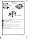
Pressure Balancing Loop 5" (127 mm) 5" (127 mm) Tee Soldering Template 1/2" NPT Nipple 1. Install the Supply Piping – Single Supply Route the water supply lines. Use the provided soldering template to construct a pressure balancing loop. Position tees in the loop over each of the four raised locations on the template. Solder the assembly while it is attached to the template. Remove the pressure balancing loop from the template. Connect the pressure balancing loop to the water supply.
Tee 5" (127 mm) 5" (127 mm) Soldering Template Rigidly connect the loops to each other while on the template. Pressure Balancing Loops 1/2" NPT Nipple 2. Install the Supply Piping – Multiple Supplies Route the water supply lines. Use the provided soldering template to construct the pressure balancing loops. Position tees in the loops over each of the four raised locations on the template. Solder the assembly while it is attached to the template.
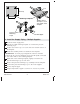
9" (229 mm) 2x4 2x4 14-1/2" (368 mm) Typical 2x2 2x2 2x4 Pressure Balancing Loop Ceiling Joist 2x4 1-3/16" (30 mm) 3. Install the Support Framing Construct the support framing as illustrated. The 2x2 should be offset 1-3/16″ (30 mm) from the bottom edge of the 2x4s to support the pressure balancing loop at the proper depth. Install the support framing under the pressure balancing loop(s). The bottom of the 2x4s should be flush with the bottom of the ceiling joists. Do not strap the pipes.
Tee 2-1/4" (57 mm) Min Finished Ceiling Cutout 9" (229 mm) 9-1/4" (235 mm) Finished Ceiling 9" (229 mm) 9-1/4" (235 mm) Cutout Tee Nipple 9" (229 mm) 9-1/4" (235 mm) 4. Install the Finished Ceiling Install the water-resistant wall board. Cut out a 9″ (229 mm) to 9-1/4″ (235 mm) square at the desired installation location. Install the finished wall material. 5. Install the Pipe Nipple Remove the nipples.
Install the Pipe Nipple (cont.) Measure the distance from the end of the nipples to the surface of the finished ceiling. Verify that the distance is at least 1-1/2″ (38 mm) and no more than 1-3/4″ (44 mm). Remove the nipples. Apply thread sealant to the threads of the nipples. Reinstall the nipples to the tees/elbows. Run water through the system to flush out any dirt or debris. Kohler Co.
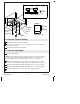
Leak Shield Escutcheon Adapter Socket Wrench With Bit Extension Waterway Screw 6. Install the Waterway Insert the escutcheon into the opening. If any of the leak shields makes contact with an elbow: Enlarge the hole in the back of the leak shield to 1-1/4″ (32 mm). Thread the adapter onto the nipple using the provided 11 mm bit, 11 mm or 7/16″ socket, extension and socket wrench. Use masking tape to hold the bit in place, as the bit could fall off and cause damage.
Install the Waterway (cont.) Repeat for the remaining waterways. Kohler Co.
Escutcheon Waterway Ribs Groove Sprayhead Hex Screws Nozzle Membrane 7. Install the Sprayhead Using a 5/32″ hex wrench, secure the sprayhead to the waterway with the two hex screws. Do not overtighten. Verify that the sprayhead sits squarely within the escutcheon and tilts freely up and down. Place the nozzle membrane over the sprayhead, aligning the long edge of the membrane with the ribs. NOTE: For optimum performance, ensure that the membrane is applied evenly.
Sprayface Ribs Setscrews Sprayface 8. Install the Sprayface NOTE: For product with brushed finishes, align the brush pattern of the sprayfaces with the direction of the brushed pattern of the escutcheon. Tilt the sprayhead to expose the ribs. Position the grooves of the sprayface over the ribs, then rotate the loose end of the sprayface up as illustrated. Press the sprayface into place to cover the sprayhead. Tilt the sprayhead assembly to expose the setscrew holes.
Warranty (cont.) (″Faucet″)*, (except gold, non-Vibrant®, non-chrome finishes) to be free of defects in material and workmanship during normal residential use for as long as the original consumer purchaser owns his or her home. This warranty applies only to Kohler Faucets installed in North America. If a defect is found in normal residential use, Kohler Co. will, at its election, repair, provide a replacement part or product, or make appropriate adjustment.
Warranty (cont.) state/province to state/province. This is Kohler Co.’s exclusive written warranty.
Warranty (cont.) 1. When the product is not operated in accordance with the instructions concerning use and operation set forth in the owner’s manual or installation instructions, and when the recommendations and warnings included are not observed. 2. When the product has been modified or dismantled partially or totally; or has been used in a negligent fashion and as a consequence has suffered damages attributable to the consumer, individual, or hardware not authorized by Kohler Co. 3.
Guide d’installation et d’entretien Panneau de pluie monté au plafond Outils Tournevis Clés cruciforme hexagonales 5/64" & 5/32" Rubancache Ruban d'étanchéité Clé à douille avec douille et rallonge de 11 mm ou de 7/16" Soudure Plus: Remarque: Tous les mamelons et raccords sont de 1/2" NPT • Fermer ou mamelon 1-1/2" • Raccords femelles • Tube en cuivre de 1/2" • 2x2 et 2x4 • Outils et matériels conventionnels de menuiserie Informations importantes AVIS: Choisir une vanne de compensation automatique av
Boucle de régulateur de pression 5" (127 mm) 5" (127 mm) T Gabarit de soudure Mamelon de 1/2" NPT 1. Installer la tuyauterie d’alimentation – Simple Acheminer les conduites d’alimentation en eau. Utiliser le gabarit de soudage fourni pour construire une boucle de régulation de pression. Positionner les tés dans la boucle sur chacun des quatre emplacements en relief sur le gabarit. Souder l’ensemble pendant qu’il est attaché sur le gabarit.
T 5" (127 mm) 5" (127 mm) Gabarit de soudure Connecter solidement les boucles les unes aux autres, en étant sur le gabarit. Boucles de régulation de pression Mamelon de 1/2" NPT 2. Installer la tuyauterie d’alimentation – Multiples Acheminer les conduites d’alimentation en eau. Utiliser le gabarit de soudage fourni pour construire les boucles de régulation de pression. Positionner les tés dans les boucles sur chacun des quatre emplacements en relief sur le gabarit.
Installer la tuyauterie d’alimentation – Multiples (cont.) Ne pas dégarnir les tuyaux. Installer un mamelon temporaire sur chaque té. Ne pas utiliser du mastic d’étanchéité. 1207715-2-B Français-4 Kohler Co.
9" (229 mm) 2x4 2x4 14-1/2" (368 mm) typique 2x2 2x2 2x4 Boucle de régulation de pression Solive de plafond 2x4 1-3/16" (30 mm) 3. Installer le cadrage de support Construire le cadrage de support tel qu’illustré. Les montants 2x2 doivent être décalés de 1-3/16″ (30 mm) par rapport au bord inférieur des montants 2x4 pour supporter la boucle de régulation de pression à la profondeur adéquate. Installer le cadrage de support sous la ou les boucles de régulation de pression.
T 2-1/4" (57 mm) Min. Plafond fini Découpe 9" (229 mm) 9-1/4" (235 mm) 9" (229 mm) 9-1/4" (235 mm) Plafond fini Découpe T Mamelon 9" (229 mm) 9-1/4" (235 mm) 4. Installer le plafond fini Installer le matériau du panneau mural hydrorésistant. Découper un carré de 9″ (229 mm) à 9-1/4″ (235 mm) à l’emplacement d’installation souhaité. Installer le matériau de la finition murale. 5. Poser le mamelon Retirer les mamelons.
Poser le mamelon (cont.) Enfiler le mamelon dans le té/coude et serrer à la main. Mesurer la distance entre l’extrémité des mamelons et la surface du plafond fini. Vérifier que la distance est égale à 1-1/2″ (38 mm) au moins et qu’elle est inférieure à 1-3/4″ (44 mm). Retirer les mamelons. Appliquer du ruban d’étanchéité pour filets sur les filets des mamelons. Réinstaller les mamelons sur les tés/coudes. Faire couler de l’eau à travers le système pour éliminer les saletés ou les débris. Kohler Co.
Protection contre fuites Applique Adaptateur Clé à douille avec mèche Extension Passage eau Vis 6. Installer le passage d’eau Insérer l’applique dans l’ouverture. Si les écrans anti-fuite entrent en contact avec un coude: Élargir le trou à l’arrière de l’écran anti-fuite à 1-1/4″ (32 mm). Enfiler l’adaptateur sur le mamelon en utilisant la mèche de 11 mm, la douille de 11 mm ou 7/16″ fournies, ainsi que la rallonge et la clé à douilles.
Installer le passage d’eau (cont.) IMPORTANT! Si l’applique est toujours lâche après cette étape, utiliser un mamelon de tuyau plus court. Répéter cette procédure pour les passages d’eau restants. Kohler Co.
Applique Passage d'eau Arrêtes Rainure Tête du vaporisateur Vis hexagonales Membrane des buses 7. Installer la tête du vaporisateur Utiliser une clé hexagonale de 5/32″ pour sécuriser la tête du vaporisateur sur le passage d’eau avec les deux vis à tête hexagonale. Ne pas trop serrer. Vérifier que la tête du vaporisateur est d’équerre avec l’applique et qu’elle bascule librement vers le haut et vers le bas.
Face du vaporisateur Arrêtes Vis de retenue Face du vaporisateur 8. Installer la face du vaporisateur REMARQUE: Dans le cas de produits avec finis brossés, aligner le motif brossé des faces du vaporisateur avec la direction du motif brossé se trouvant sur l’applique. Incliner la tête du vaporisateur pour exposer les nervures. Positionner les rainures de la face du vaporisateur par-dessus les nervures, puis tourner l’extrémité lâche de la face du vaporisateur tel qu’illustré.
Garantie (cont.) l’acheteur, sans frais, la cartouche nécessaire pour réparer le robinet. La présente garantie s’applique uniquement aux robinets Kohler installés aux États-Unis, au Canada ou au Mexique (″Amérique du Nord″). Kohler Co.
Garantie (cont.) GARANTIES TACITES DE COMMERCIALITÉ ET D’ADAPTATION À UN USAGE PARTICULIER. KOHLER CO. ET/OU LE REVENDEUR DÉCLINENT TOUTE RESPONSABILITÉ CONTRE LES DOMMAGES PARTICULIERS, ACCESSOIRES OU INDIRECTS. Certains états et provinces ne permettent pas de limite sur la durée de la garantie tacite, ni l’exclusion ou la limite des dommages, et, par conséquent, lesdites limites et exclusions peuvent ne pas s’appliquer à votre cas.
Guía de instalación y cuidado Panel de lluvia de instalación al techo Herramientas Más: Nota: Todas las conexiones y niples son de 1/2" NPT Destornillador Llaves Cinta de • Niple corto o de 1-1/2" Phillips hexagonales enmascarar • Conectores hembra de 5/64" y • Tubería de cobre de 1/2" Cinta 5/32" • Listones de 2x2 y 2x4 selladora • Herramientas y materiales convencionales de carpintería Llave de dados con extensión Materiales para soldar y dado de 11 mm o 7/16" Información importante AVISO: Seleccione una
Bucle de regulación de presión 5" (127 mm) 5" (127 mm) T Plantilla de soldar Niple de 1/2" NPT 1. Instale la tubería de suministro – Un suministro Tienda las líneas de suministro de agua. Utilice la plantilla de soldar provista para construir un bucle de regulación de presión. Coloque Tes en el bucle sobre cada una de las cuatro ubicaciones elevadas en la plantilla. Suelde el ensamble mientras está fijo a la plantilla. Retire el bucle de regulación de presión de la plantilla.
T 5" (127 mm) 5" (127 mm) Plantilla de soldar Conecte rígidamente los bucles uno al otro, mientras están en la plantilla. Bucles de regulación de presión Niple de 1/2" NPT 2. Instale la tubería de suministro – Múltiples Tienda las líneas de suministro de agua. Utilice la plantilla de soldar provista para construir los bucles de regulación de presión. Coloque las Tes en los bucles sobre cada una de las cuatro ubicaciones elevadas en la plantilla. Suelde el ensamble mientras está fijo a la plantilla.
Instale la tubería de suministro – Múltiples (cont.) No coloque abrazaderas en los tubos. Instale provisionalmente un niple en cada T. No utilice ningún sellador. Kohler Co.
9" (229 mm) 2x4 2x4 14-1/2" (368 mm) Típico 2x2 2x2 2x4 Bucle de regulación de presión Viga del techo 2x4 1-3/16" (30 mm) 3. Instale la estructura de soporte Construya la estructura de soporte como se ilustra. El poste de madera de 2x2 debe estar descentrado 1-3/16″ (30 mm) desde el filo inferior de los postes de 2x4 para soportar el bucle de regulación de presión a la profundidad correcta. Instale la estructura de soporte debajo del bucle o bucles de regulación de presión.
T 2-1/4" (57 mm) Mín Techo acabado Abertura 9" (229 mm) 9-1/4" (235 mm) Techo acabado 9" (229 mm) 9-1/4" (235 mm) Abertura T Niple 9" (229 mm) 9-1/4" (235 mm) 4. Instale el techo acabado Instale el panel de pared resistente al agua. Corte un cuadro de 9″ (229 mm) a 9-1/4″ (235 mm) en el lugar de instalación deseado. Instale el material de acabado de la pared. 5. Instale el niple Retire los niples.
Instale el niple (cont.) Mida la distancia desde el extremo del niple hasta la superficie del techo acabado. Verifique que la distancia sea por lo menos 1-1/2″ (38 mm) pero no mayor de 1-3/4″ (44 mm). Retire los niples. Aplique sellador de roscas a las roscas del niple. Vuelva a instalar los niples a las Tes/codos. Deje correr agua a través del sistema para eliminar las suciedad y los residuos. 1207715-2-B Español-7 Kohler Co.
Protector contra fuga Chapetón Adaptador Llave de dados con broca Extensión Vía de agua Tornillo 6. Instale la vía de agua Inserte el chapetón en la abertura. Si alguno de los protectores contra fugas entra en contacto con un codo: Agrande el orificio a 1-1/4″ (32 mm) en el lado posterior del protector contra fugas. Enrosque el adaptador al niple utilizando la llave de dados, extensión y dado de 11 mm o 7/16″, o la broca de 11 mm provista.
Instale la vía de agua (cont.) ¡IMPORTANTE! Si después de este paso, el chapetón aún está suelto, utilice un niple más corto. Repita el procedimiento con las otras vías de agua. 1207715-2-B Español-9 Kohler Co.
Chapetón Vía de agua Salientes Ranura Cabeza del rociador Tornillos hexagonales Membrana de boquillas 7. Instale la cabeza del rociador Con la llave hexagonal de 5/32″, fije la cabeza del rociador a la vía de agua con los dos tornillos hexagonales. No apriete demasiado. Verifique que la cabeza del rociador quede encuadrada en el chapetón y que se incline libremente hacia arriba o hacia abajo.
Placa exterior del rociador Salientes Placa exterior del rociador Tornillos de fijación 8. Instale la placa exterior del rociador NOTA: Para el producto de acabado cepillado, alinee el diseño del cepillado de la placa exterior de los rociadores con la dirección del diseño del cepillado del chapetón. Incline la cabeza del rociador para exponer las salientes.
Garantía (cont.) propietario de su casa. En caso de que la Grifería presente fugas o goteo durante el uso normal, Kohler Co. enviará por correo y sin ningún cargo al comprador original, el cartucho necesario para que la Grifería funcione correctamente. Esta garantía se aplica sólo a la Grifería Kohler instalada en los Estados Unidos de América, Canadá o México (″Norteamérica″). Kohler Co.
Garantía (cont.) QUE SUSTITUYEN TODAS LAS DEMÁS GARANTÍAS, EXPRESAS O IMPLÍCITAS, INCLUYENDO, ENTRE OTRAS, LAS GARANTÍAS IMPLÍCITAS DE COMERCIALIZACIÓN E IDONEIDAD PARA UN USO DETERMINADO. KOHLER CO. Y/O EL VENDEDOR DESCARGAN TODA RESPONSABILIDAD POR CONCEPTO DE DAÑOS PARTICULARES, INCIDENTALES O INDIRECTOS.
Garantía (cont.) 3. Kohler Co., a través de sus distribuidores autorizados, se compromete a reparar el producto defectuoso o, cuando la reparación no sea posible, reemplazarlo por uno nuevo o un modelo equivalente (en caso de que el producto haya sido descontinuado) sin ningún cargo al consumidor. 4. El tiempo de reparación no excederá de seis (6) semanas a partir de la fecha de recepción del producto. 5.
1207715-2-B
1207715-2-B
USA/Canada: 1-800-4KOHLER México: 001-800-456-4537 kohler.com ©2013 Kohler Co.