
Transfer Switch Spec Sheet
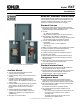

G11-140 (Model RXT Automatic Transfer Switch) 3/20g Page 2
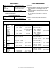
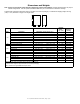
Specifications
Standard Interface Board
Controller interface connections
AandB
#20 AWG shielded twisted-pair
Belden 9402 or 8762 or equivalent
Controller interface connections
PWR and COM
#12- 20 AWG
(see ATS Installation Manual)
Load control contact rating 10 A @ 250 VAC
Load control connections #12- 18 AWG
Note: For combined interface/load management board
specifications, see page 3.
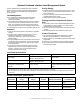
Environmental Specifications
Operating temperature
−
20_Cto70_C(
−
4_F to 158_F)
Storage temperature
−
40_Cto85_C(
−
40_F to 185_F)
Humidity
5 to 95% noncondensing
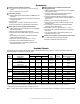
Codes and Standards
The ATS meets or exceeds the requirements of the following
specifications:
D Underwriters Laboratories UL 1008, Standard for Automatic
Transfer Switches for Use in Emergency Systems, file
#E58962
D Underwriters Laboratories UL 508, Standard for Industrial
Control Equipment
D CSA certification available, file # LR58301 (not available for
150, 300, or 400 amp service entrance or 100 amp load
center models). Must be selected when the transfer switch
is ordered.
D NFPA 70, National Electrical Code
D NFPA 110, Emergency and Standby Power Systems
D NEMA Standard IC10- 1993, AC Automatic Transfer
Switches
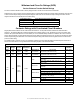
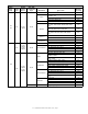
Cable Sizes
AL/CU UL-Listed Solderless Screw-Type Terminals for External Power Connections
Switch
Size,
Amps
Switch Phases
Range of Wire Sizes, Cu/Al
Normal and Emergency Load Neutral Ground
100
Standard 1 (1) #14 - 1/0 AWG (1) #14 – 1/0 AWG
(5)#12to250KCMIL(Cu)or
(5) #10 to 250 KCMIL (Al)
(9) #6 – #14 AWG
(4) #14 - 1/0 AWG
12- or 16-
space load
center
(NEMA 1)
1 (1) #14 – 1/0 AWG
per customer-supplied
circuit breaker
(26) #4 - 14 AWG or
(2) #14 - 1/0 AWG or
(1) #6 – 2/0 AWG
16-space
load center
(NEMA 3R)
1 (1) #14 – 1/0 AWG
per customer-supplied
circuit breaker
(26) #4 - 14 AWG or
(2) #14 - 1/0 AWG or
(1) 2/0 AWG
Service
Entrance
1
Normal: (1) #12 – 2/0 AWG
Emerg: (1) #14 – 1/0 AWG
(1) #14 – 1/0 AWG
(5)#12to250KCMIL(Cu)or
(5) #10 to 250 KCMIL (Al)
(4) #14 – 1/0 AWG
(9) #14 - #6 AWG
3-Phase 3 (1) #14 – 1/0 AWG (1) #14 – 1/0 AWG
(3)#4AWG–600KCMIL
(6) 1/0 AWG – 250 KCMIL
150
200
Service
Entrance
1
Normal: (1) #4 – 300 KCMIL
Emerg: (1) #6 - 250 KCMIL
(1) #6 – 250 KCMIL
(5)#12to250KCMIL(Cu)or
(5) #10 to 250 KCMIL (Al)
200
Standard 1
(1) #6 AWG – 250 KCMIL (1) #6 – 250 KCMIL
(5)#12to250KCMIL(Cu)or
(5) #10 to 250 KCMIL (Al)
(9)#14–#4AWG
(4) #14 - 1/0 AWG
3-Phase 3
300
400
Service
Entrance
1
Normal: : (1) #1 - 600 KCMIL
or (2) #1 – 250 KCMIL
Emerg: (2) #6 - 250 KCMIL
(2) #6 – 250 KCMIL
(3)#4AWG–600KCMIL
(6) 1/0 AWG – 250 KCMIL
(6) #6 – 3/0 AWG
400
Standard 1
(2) #6 – 250 KCMIL (2) #6 – 250 KCMIL
(3)#4AWG–600KCMIL
(6) 1/0 AWG – 250 KCMIL
(6) #6 – 3/0 AWG
3-pole
208-240 V
3
3or4pole
480 V
3
(1) #4 – 600 KCMIL
(2) 1/0 – 250 KCMIL
(1) #4 – 600 KCMIL
(2) 1/0 – 250 KCMIL
Note: Data is subject to change. Refer to the transfer switch dimension drawings and wiring diagrams for planning and installation.