
Installation Guide

TT-1569 6/12 3
Installation Procedure
1. Disconnect the utility power coming into the
generator set by opening the circuit breaker(s).
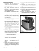
2. Open the enclosure roof.
3. Press the OFF button on the generator set
controller.
4. Remove two (2) screws on the intake panel and
remove the panel. See Figure 4.
5. Model 20RES/RESL: Unplug the battery charger.
6. Disconnect the generator set engine starting
battery(ies), negative (--) lead first.
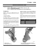
7. See Figure 2 or Figure 3. Remove the screw(s)
that secure the fuel regulator to the mounting
bracket. Keep the nut(s), which will be re-used.
Discard the screw(s).
Note: The RESA/RESAL models use one screw
and one nut. See Figure 2.
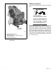
8. Before attaching heater pad GM79142 to the
regulator, hold the pad and regulator in place as
shown in Figure 2 or Figure 3. Rotate the heater
pad, if necessary, to ensure that the power cord
reaches the power receptacle without rubbing
against any sharp edges.
9. Remove the backing from the mounting adhesive
on heater pad GM79142 and press the heater pad
onto the fuel regulator.
10. Reinstall the regulator onto the mounting bracket
using screw(s) M933-06040-60, spacer(s)
265861, and the nuts that were removed in step 7.
Install the spacer(s) between the regulator and the
mounting bracket. See Figure 2 or Figure 3.
Note: 20RESA/RESAL: Discard the extra screw
and spacer provided with the kit.
11. Model 20RESA/RESAL: Remove and discard the
existing plug from the opening in the bulkhead.
See Figure 2. Insert bushing X-634-28.
12. Route the power cord to avoid contact with any
sharp edges. Use the cable ties X-468-2, provided
with the kit, to secure the power cord. See
Figure 2.
13. Plug the heater’s power cord into the 120 VAC
receptacle. Use receptacle adapter GM84773,
provided with the kit, if the battery charger or other
generator set accessories will be plugged into the
same receptacle.
14. Reconnect the engine starting battery, negative (--)
lead last.
15. 20RES/RESL: Plug the battery charger’s power
cord into the receptacle or the receptacle adapter, if
used.
16. Replace the air intake end panel and secure with
two screws.
17. Reconnect the utility power to the generator set by
closing the circuit breaker(s).
18. Press the AUTO button on the generator set
controller to put the system into automatic mode.
19. Close the roof and lock the enclosure.
TP6735
1. Roof
2. Intake panel screws (2 ea.)
3. Intake panel
1
3
2
Figure 4 Enclosure Roof and Air Intake Panel