
Manual

4 TT-1596 3/15
1 Installation Procedure
Read the entire installation procedure and compare the
kit parts with the parts list at the end of this publication
before beginning installation. Perform the steps in the
order shown.
For the generator sets, transfer switch, LCM or load
shed kit, and other accessories, refer to the installation
instructions provided with each component during this
procedure.
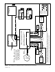
Refer to the block d iagram in Figure 7 and the APM
dimension drawings in Section 8 as needed during
installation.
1.1 Install the generato r sets and current
transformers (CTs).
1. Install the generator sets according to the
instructions and diagrams in the generator set
Installation Manual. Do not connect the wiring to
the transfer switch at this time.
2. Identify the generator sets as generator 1 and
generator 2. Use the decals provided to label
Generator 1 and Generator 2.
Note: Be careful to keep track of generator 1 and
generator 2 during the installation and
connection procedures.
3. Install one current transformer (CT) (GM86609)
inside each generator set enclosure. Install the CT
below the customer-connection terminal block in
the air intake area of the generator set.
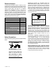
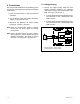
a. Load lead L1 from the generator should enter
the CT on the side with the dot. See Figure 5.
b. Load lead L2 must pass through the CT in the
opposite direction from L1 as shown in
Figure 5.
Note: Do not operate the paralleling system without the
CTs in place. The CTs are used to measure
power on each generator to allow the load to be
shared.
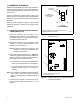
4. Connect the CT harness to connector P3 on the
RDC2 controller inside the generator set. See
Figure 6.
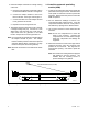
GM81374
L1 L2
L2
L1
CT DETAIL
(shown from side
for clarity)
Emergency leads must cross through the CT in
opposite directions as shown.
Dot on CT,
this side
FROM GENERATOR
TO LOAD
CIRCUIT BREAKER
Figure 5 Load Lead Routing through Current
Transformer (CT)
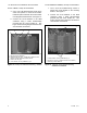
2
1. Adaptor harness connection to P2
2. CT connection to P3
GM81217
1
Figure 6 Current Transformer and Adaptor Harness
Connections to RDC2