
Load Shed Kit Spec Sheet

2013, 2015 by Kohler Co. All rights reserved.
DISTRIBUTED BY:
G11-124 (Load Shed Kit for RXT/RDT) 10/15c
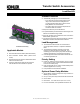
Operation
D Loads are automatically added or disconnected based on generator capacity.
D The Kohler-patented load control system uses dynamic logic to prevent shedding important loads unnecessarily when air
conditioning, refrigerator, or water pump motors start.
D The load shed kit and generator communicate to provide smart power management. The time to shed loads decreases as each
load is shed to quickly adapt to critical power requirements.
D Load shed power level and frequency setpoint adjustments are possible only by using Kohlerr SiteTecht software, available to
Kohler-authorized distributors and dealers.
Load Monitoring with OnCuer Plus
D Using Kohler’s OnCuer Plus Generator Management System (sold separately), the customer can view load status (On or Off)
for loads connected to the Load Shed Kit.
D The Load Shed Kit outputs can be labeled in OnCuer Plus.
Specifications
Connection Rating Connection
Pilot Relays* and HVAC Relays (qty. 2)
125VAC, 10 A (general purpose)
120VAC, 125VA (pilot duty)
Connect to #6 screw on terminal block
RBUS Communication and Power Con-
nections to the RDC2/DC2 controller
0.5 A @ 12 VDC
Use Belden #9402 or equivalent 20 AWG
shielded, twisted-pair communications cable
[
* Four (4) pilot relays are provided for customer-supplied load-switching contactors/relays. Customer-supplied relays must be normally closed,
max. 50 amps. Kohler Power Relay Modules are recommended.
[ For long distances, use an equivalent shielded, twisted pair cable for RBUS connections and individual 12--20 AWG wires (qty. 2) for power
connections. A communication harness for the Model RXT transfer switch is included with the load shed kit. See TT--1609, Load Shed Kit
Installation Instructions, for details.
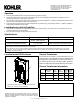
Location Inside ATS Enclosure
1
1. Typical location of load shed kit. Location varies with transfer
switch model. (cover removed for illustration)
Current Transformer
The load shed kit includes a current transfomer (CT) for
load monitoring. If the application requires cables that are
too large for the inner diameter (I.D.) of the CT provided, or
you need a 500 Amp CT for use with a 60RCL generator,
please see table below for optional sales kit part numbers.
Current Transformer Information
Sales Kit Part
Number
Service
Part
Number
Ratio
(Amps:VAC)
Outer
Diameter
mm (in.)
Inner
Diameter
mm (in.)
Incl uded
with Kit
N/A GM83929 400:3
63.5
(2.5)
28.7
(1.13)
Sold
Separately
GM17250-KP1-QS GM17250 400:3
111.8
(4.4)
57.2
(2.25)
Sold
Separately
GM17250-KP2-QS GM60264 500:3
171.5
(6.75)
108.0
(4.25)
Availability is subject to change without notice. Kohler Co. reserves the
right to change the design or specifications without notice and without any
obligation or liability whatsoever. Contact your local Kohlerr generator
distributor for availability.
KOHLER CO., Kohler, Wisconsin 53044 USA
Phone 920-457-4441, Fax 920-459-1646
For the nearest sales and service outlet in the
US and Canada, phone 1-800-544-2444
KOHLERPower.com