
Install Manual


TT-1646 6/15 3
1.3 Relay Connections to a Load Shed Kit
This section applies to models RDT ATS and RXT ATS
equipped with load shed kit GM88281-KA1 or
GM88281-KP1-QS. For the RXT with combined
interface/load management board, go to Section 1.4.
See Figure 2 for cable specifications.
Note: See the instructions provided with the load shed
kit for load priority and load management
operation information.
Load management priorities are determined by the
control relay output connections to the load shed kit.
Typically, Load A is added first and shed last.
1. Disconnect power to the transfer switch.
2. If the load shed kit is not already installed, follow the
instructions provided with the load shed kit to install
the load shed kit into the transfer switch enclosure
and connect it to the generator set controller and
current transformer.
3. Connect customer-supplied leads to the control
relay output terminals on the load shed kit terminal
block. See Figure 3 and Figure 4.
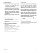
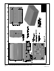
4. See Figure 7 for the coil connection screws on the
relay. Connect the control leads from the load shed
kit to the relay coil using ring terminals X-283-2.
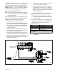
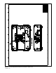
5. See Figure 4 and Figure 8 for the source and load
connections to the relay.
a. Connect the line side of the relay to the source
power circuit as shown in Figure 4.
b. Connect the load side of the relay to the
non-essential load circuits as shown in
Figure 4. Two (2) 120 VAC loads (shed
simultaneously) or a single 240 VAC load can
be wired to each relay.
6. Connect the 120 VAC power circuit to the the load
shed kit terminal block as shown in Figure 4.
Note: The AC power supply circuit must be
protected by an appropriately sized fuse or
circuit breaker.
7. For all other load shed kit installation and
connection instructions, see the installation
instructions provided with the load shed kit.
8. Go to Section 1.5.
Relay * Load Shed Kit TB10 Connection
Load A TB10-1 and TB10-2
Load B TB10-3 and TB10-4
Load C TB10-5 and TB10-6
Load D TB10-7 and TB10-8
* Load add/shed priority is based on the order of connection to
the terminal block.
Figure 3 Relay Coil Control Connections to Load
Shed Kit
GM88804
LOAD SHED KIT
TERMINAL BLOCK
FACTORY CONNECTIONS
RBUS
CONNECTIONS
Figure 4 Relay Connections to Load Shed Kit