
Install Manual


TT-1646 6/15 5
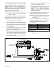
1.5 Ground the box.
Note: The power relay module uses a non-conductive
resin enclosure. Bonding between conduit
connections is not automatic and must be
provided as part of the installation.
1. Connect ground leads to the 1/4-20 post near the
bottom of the box using nut X-81-8. See Figure 7.
If metal conduit is used, use conduit hubs with
screw terminals for the ground connection.
Connect the ground leads LK-1006-1515, supplied
with the kit, to the grounding post. Connect the
other ends of the g round leads to the conduit hub
screw terminals.
2. Ground the system according to the NEC and
applicable state and local codes.
1.6 Install the module cover.
1. Check that gasket GM92009 is in place in the
groove around the edge of the box, with a gap at the
bottom as shown in Figure 7 .
2. Place the cover on the box and reinstall the four
cover screws.
1.7 Return the system to automatic
operation.
1. Check that the generator set is OFF.
2. Reconnect the generator set engine starting
battery, negative (--) lead last.
3. Reconnect utility power to the generator set.
4. Press the AUTO button on the generator set
controller.
5. Reconnect power to the transfer switch.
2 Operation
The power relay module operation is controlled by the
load management device, which is either a load shed kit
or the RXT combined interface/load management
board. The relay is normally closed so that the
connected load is powered when the normal source is
available.
When the transfer switch is in the emergency source
position and power is supplied by the generator set, the
load management device signals the relay to open or
close. When the relay is open, the load is not powered.
When the relay closes, the load is powered by the
generator set. The loads are prioritized according to the
relay connections to the load management device. See
TT-1609 for the load shed kit or TP-6807, RXT ATS
Operation/Installation Manual, for information about
operation of the load management device.
Note: The power relay modules are not RBUS
modules.
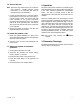
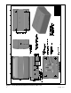
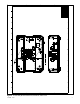
3 Dimension Drawings
The dimension drawings for the power relay module a re
shown in Figure 7 and Figure 8.