
Installation Guide


3. Amplifier Connection
NOTE: The transducer terminals and wires are numbered to
identify the correct connections. When required, the amplifier can be
removed to aid in the wire connection process.
NOTE: A data cable is provided to connect the amplifier to the user
interface.
NOTICE: The circular auxiliary-in port is not an ethernet
communication port. Do not connect an ethernet network to the
auxiliary-in port. Use the auxiliary-in port only for a standard
accessory.
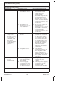
Disconnect the power from the amplifier.
If equipped, connect the chromatherapy connector from the bath
to the chromatherapy connection on the amplifier.
Connect the transducer wires to the transducer terminals on the
amplifier. The white wires with black stripes are connected to the
positive (+) terminals, and the solid white wires are connected to
the negative (-) terminals.
Connect the clear connector of the user interface cable to the
amplifier user interface connection.
If used, connect the auxiliary-in cable to the auxiliary-in port on
the amplifier.
Reconnect the power to the amplifier.
Verify that the status LED turns on.
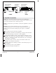
Power
Cable
Transducer
Terminals
User Interface
Connection
BACKFRONT
Auxiliary-In
Port
Chromatherapy
Connection
Status LED
Kohler Co. 7 1298482-2-A