
Installation Guide
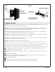

3. Make Electrical Connections
NOTE: The product model number is printed on a label on the blower side of the bath. This label also
identifies the electrical rating of the product. All baths come equipped with a wiring junction box and
are designed to operate between 220 V and 240 V at either 50 Hz or 60 Hz.
WARNING: Risk of electric shock. Disconnect the power before performing the following
procedures.
WARNING: Risk of electric shock. Connect the blower to a properly grounded Ground-Fault
Circuit-Interrupter (GFCI) or Residual Current Device (RCD). This will provide additional
protection against line-to-ground shock hazard. A 220-240 V, 20 A, 50/60 Hz dedicated circuit is
required.
IMPORTANT! The load neutral is not used. There should be no connection to the load neutral terminal
on the Ground-Fault Circuit-Interrupter (GFCI) breaker. The green wire with the yellow stripe is the
equipment ground and needs to be connected to the neutral bus in the main circuit breaker box.
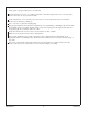
IMPORTANT! Some equipment and installations vary. Refer to ″Alternate Wiring Connection″ as shown.
NOTE: The wiring harness includes an antenna for the optional remote control. Do not alter or damage
this antenna during installation.
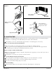
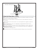
Blue
(L1)
Ground
(Green with
Yellow Stripes)
From Heated
Surface
Brown (L2)
Provide suitable
strain relief.
Typical Wiring Connection
Control
Check Valve
Blower Motor Cord
Control
Power Supply
External Power
Field Wiring
(From Junction Box
to GFCI Breaker)
*Equipment
Ground
*Line Neutral
(White Wire)
Neutral
Bus
240 V
120 V
*L2
240 V
*L1
Two-Pole Circuit
Breaker with GFCI
Breaker Box
L2
L1
N
120/240 VAC Source
No Connection
(Load Neutral)
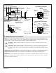
Ground
(Green)
Black (L1)
From Control
White
(Neutral)
Junction
Box
Blue
(L1)
Ground
(Green with
Yellow Stripes)
From Heated
Surface
Brown (L2)
Black or Brown
From Control
White or
Blue
(Neutral)
Alternate Wiring Connection
Bond in accordance
with local codes.
*Connections at the
Circuit Breaker
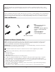
Wire
Connector
Wire
Connector
1204120-2-D 8 Kohler Co.