
Installation Guide

2. Determine the Location of the Steam Hardware
WARNING: Risk of personal injury. Do not install the steam control user interface outside the
steam enclosure. The user interface must be installed within the enclosure to allow the sensors to
regulate the temperature and control the flow of steam.
WARNING: Risk of scalding. Do not block the steam head or locate it near a seat or bench, as the
steam head is hot during operation and may scald the user if touched.
IMPORTANT! Do not install the control directly above or in-line with the steam head.
NOTICE: When installing the control kit, allow room in the control cable for a drip loop. The drip loop
will discourage moisture from following the control cable to the steam generator.
NOTE: All dimensions should be taken from the inside of the shower. Refer to the Steam Control Kit
Installation Guide for more dimensional and installation information.
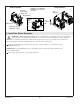
Dual steam heads can be installed on opposite walls to improve steam distribution.
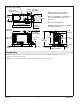
Determine the steam head location. Locate the steam head(s) 6″ (152 mm) above the shower floor
and a minimum of 4-1/2″ (114 mm) away from the enclosure door threshold. The steam head
location should be within 25’ (7.62 m) of the steam generator.
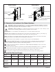
For single steam head installations, determine the steam control user interface location on the wall
opposite the steam head.
For dual steam head installations, determine the steam control user interface location on a different
wall than the steam heads. Locate the user interface as far from the steam heads as practical.
Locate the steam control user interface 60″ (1524 mm) above the floor of the shower.
Make sure there is adequate clearance between the steam lines and any surrounding surfaces.
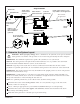
3. Install the Electrical Supply
Model K-5525-NA K-5526-NA K-5529-NA K-5531-NA K-5539-NA K-5543-NA
Generator Size 5 kW 7 kW 9 kW 11 kW 18 kW (2 - 9
kW)
22 kW (2 - 11
kW)
Required Electrical Service
Generator
Dedicated
Circuit #1
240 V, 40 A,
50/60 Hz
240 V, 50 A,
50/60 Hz
240 V, 60 A,
50/60 Hz
240 V, 60 A,
50/60 Hz
240 V, 60 A,
50/60 Hz
240 V, 60 A,
50/60 Hz
Generator
Dedicated
Circuit #2
NA NA NA NA 240 V, 60 A,
50/60 Hz
240 V, 60 A,
50/60 Hz
12-1/2" (318 mm) Min
Provide
clearance
from wall.
Wall Stud
6" (152 mm) from Floor
2-1/2" (64 mm)
Single Installation
2-1/2" (64 mm)
Provide clearance
from wall.
6" (152 mm) from Floor
Wall Stud
2" (51 mm) Min
Dual Installation
2" (51 mm) Min
1230487-2-C 8 Kohler Co.