
Specification


Required Accessories
K-304-* Rite-Temp
®
pressure-balancing valve OR ❑ NA
K-2971-KS HiFlow Rite-Temp valve with stops OR ❑ NA
K-11748-* Rite-Temp valve with push-button diverter ❑ NA
* For a complete listing of all the Rite-Temp valves, refer to the individual valve Specification Sheet or Roughing-In Sheet.
Optional Accessories
1151968 Deep roughing-in kit for Rite-Temp valve ❑ CP ❑ Other ____
Installation Notes
Install the valve trim according to the installation guide.
Install the Rite-Temp valve according to the installation guide.
NOTICE: Risk of product damage. For K-2971-KS valve:
1-5/8″ (4.1 cm) screws (included) must be used. 2-3/8″ (6 cm)
screws will damage the valve.
Avoid cross-flow conditions. Do not install a shut-off device on
either valve outlet.
Cap the shower outlet if the deck-mounted spout, diverter, or
handshower is connected to the spout outlet.
Install a 7″ (17.8 cm) to 18″ (45.7 cm) straight pipe or straight
tube with single elbow between the valve and the wall-mount
spout.
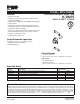
4" (10.2 cm)
to Top of Rim
6-3/4" (17.1 cm)
4-3/16"
(10.6 cm)
1/2" NPT
1/2" Hot
1/2" Cold
10" (25.4 cm)
to Spout
(Bath Only)
6-1/2"
(16.5 cm) D.
For slip-fit spout, 1/2" nominal
tube must extend 3-3/4" (9.5 cm)
beyond finished wall.
For threaded spout, 1/2" NPT
pipe nipple must extend 3-7/8"
(9.8 cm) beyond finished wall.
72" (182.9 cm) -
78" (198.1 cm)
to floor (Typical)
48" (121.9 cm)
to floor
(Shower Only)
1-1/2" (3.8 cm) D.
Max Hole in the Wall.
Supply tube must
be centered in the
hole.
10"
(25.4 cm)
1/2" NPT pipe nipple
must extend 5/8" (1.6 cm)
beyond finished wall.
1-1/4" (3.2 cm) D.
Max Hole in the wall.
2-5/8"
(6.7 cm)
4-7/16"
(11.3 cm)
C
L of Valve Inlet
2-3/4" (7 cm) Thin Wall
3-1/2" (8.9 cm) Thick Wall
If over 3-1/2" (8.9 cm) and
up to 4-1/2" (11.4 cm),
use Deep Roughing-in kit.
Product Diagram
TOOBITM RITE-TEMP
®
TOOBITM RITE-TEMP
®
BATH AND SHOWER VALVE TRIM
Page2of2
1152819-4-
B