
Spec Sheet


G11-141 (Model KEP Service Entrance Rated Transfer Switch) 1/18d Page 5
Accessories
Accessories are available either factory-installed or as loose
kits, unless otherwise noted.
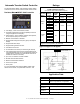
- Digital Meter *
D Measure and display voltage, current, frequency, and
power for both sources:
D Programmable visual alarms for high voltage, low voltage,
and high current
D Three digital outputs
D Serial port for optional network connections
D Password-protected programming menus
D Joystick operation
D Factory-installed
* Meter kit not available on MCCB models with NEMA 3R enclosures.
- Heater, Anti-Condensation
D Hygrostat-controlled 120 VAC strip heater
(customer-supplied voltage source required)
D 100 or 250 watts (sized for enclosure)
D Protective 15 Amp circuit breaker
- Literature Kits
D Production literature kit
(one set of literature is included with each transfer switch)
D Overhaul literature kit
- RSA III Remote Serial Annunciator
D Monitors the generator set
D Monitors Normal and Emergency source status and
connection
D Monitors ATS common alarm
D Allows remote testing of the ATS
D For more information, see specification sheet G6--139.
- Seismic Certification
D Certification depends on application and geographic
location. Contact your distributor for details.
D Available for the transfer switches and enclosures shown
below:
ATS Type and Size Enclosure, NEMA Type:
Type Amps 1 3R 4X 12
MCCB 100--600
D
MCCB 100--1200
D D D
ICCB 800--4000
D D
- Surge Protection Device (SPD)
D SPD available for the normal source supply
D Surge protection reduces transient voltages to harmless
levels
D Protection modes: L-L / L-N / L-G / N-G
D Replaceable phase and neutral cartridges for service
D Frequency: 50--60 Hz
D Operating Temperature Range: --40 to 176_F
(--40to80_C)
D Remote contacts for customer-supplied status indicators:
Contacts: 1 NO, 1 NC
Min Load: 12VDC / 10 mA
Max. Load: 250 VAC / 1 A
Wire Size (max.): 16AWG
D Fuse protection: 30 amps / 600 V
D UL 1449, 3rd Edition for Type 2 applications
D IEC 61-643-1, 2nd Edition T2/11
D See additional specifications below
- Extended Warranties
D 2-year basic
D 5-year basic
D 5-year comprehensive
D 10-year major components
Additional Controller Accessories
See the controller specification sheet for more information.
- Accessory Modules
D Alarm Module
D External Battery Supply Module
D Input/Output Module
D High-Power Input/Output Module
- Current Sensing Kit
- Line-to-Neutral Voltage Monitoring
- Padlockable User Interface Cover
- Supervised Transfer Control Switch
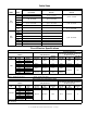
SPD Specifications
Nominal
Voltage
(V ±15%)
Max.
Discharge
Current
(kA)
Phase Poles
UL VPR 3rd Ed
(L-N/N-G/L-G)
(kV)
Limiting Voltage, (L-N/N-G/L-G)
(kV)
Short Circuit
Withstand
Current (kA)
Maximum
Continuous
Operating
V
oltage (
V
AC)
at 3kAmps at 10kAmp
240 /120 40 Split 3 0.6 / 1.2 / 0.7 0.6 / 0.4 / 0.6 0.8 / 0.7 / 0.8 200 175 / 350
208 /120 40 Wye 4 0.6 / 1.2 / 0.7 0.6 / 0.4 / 0.6 0.8 / 0.7 / 0.8 200 175 / 350
480 /277 40 Wye 4 1.0 / 1.2 / 1.1 1.0 / 0.4 / 1.0 1.2 / 0.7 / 1.2 200 320 / 460
240 /120 40 HLD 4 1.0 / 1.2 / 1.1 1.0 / 0.4 / 1.0 1.2 / 0.7 / 1.2 200 320 / 460
600 /347 40 Wye 4 1.3 / 1.2 / 1.4 1.3 / 0.4 / 1.3 1.5 / 0.7 / 1.5 200 440 / 880