EN ESS PRO 3.7, PRO 3.7 E, PRO 5.2, PRO 5.2 E, PRO 7.5, PRO 7.5 E Generator Owner's Manual IMPORTANT: Read all safety precautions and instructions carefully before operating equipment. Ensure engine is stopped and level before performing any maintenance or service. Record product information to reference when ordering parts or obtaining warranty coverage. Specification Serial Number Purchase Date 37 590 01 Rev. I KohlerPower.
Safety Precautions DANGER: A hazard that will result in death, serious injury, or substantial property damage. WARNING: A hazard that could result in death, serious injury, or substantial property damage. CAUTION: A hazard that could result in minor personal injury or property damage. NOTE: is used to notify people of important installation, operation, or maintenance information. Read this manual carefully before operating this machine. This manual should stay with this machine if it is sold.
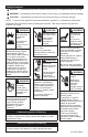
EN Important Labels on Generator DANGER Using a generator indoors CAN KILL YOU IN MINUTES. Generator exhaust contains carbon monoxide. This is a poison you cannot see or smell. NEVER use inside a home or garage, EVEN IF doors and windows are open. Only use OUTSIDE and far away from windows, doors, and vents. Avoid other generator hazards. READ MANUAL BEFORE USE. WARNING / ADVERTENCIA / AVERTISSEMENT ● Do not touch generator while operating or just after stopping.
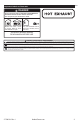
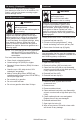
A B E E E E E F V U I J C AE AC Y D G G H W T AD K Z AA AB N M O S L X Q P R A Circuit Breaker B Maintenance Minder C 240/120V/30A Electrical Socket D 120V/30A Electrical Socket E Circuit Protector F 12V DC Receptacle3 G GFCI Receptacle H Ground Terminal I Auto Idle3 J On/Off/Start Switch K Fuel Tank Cap L Fuel Level Indicator M Oil Drain Plug N Oil Fill Plug/ Dipstick O Starter Battery3 P Choke Lever Q Spark Plug R Carbon Canister S Starter Han
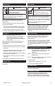
1. Turn main AC circuit breaker (A) OFF. Pre-Start Checklist 1. Ensure generator is at least 3.3 ft. (1 m) from building or other equipment and not covered with any material. 3. Turn Fuel (X) ON. 2. Refer to all warning labels prior to starting. 4. Turn engine to ON (J) and pull rope (or push start button (J) for electric start). 3. Check oil level using oil fill plug (N). Add oil if low. Do not overfill. 5. Turn choke lever (P) OFF after engine is warm. 4. Check fuel level indicator (L).
Cable Selection Generator Socket Type mm2 AWG mm2 AWG 32 A AWG 16 A mm2 Recommended Cable Cross Section 10 A 4 Length of 51 to Cable 100 m 10 Used 101 to 150 m1 10 10 6 9 10 7 7 10 7 25 3 7 16 5 35 2 0 to 50 m This cable length is maximum permitted length, and must not be exceeded. 1 Installation method=cables on raceway or non-drilled tablet/Permitted drop in voltage=5%/Multi-core conductors/Cable type PVC 70°C (e.g. H07RNF)/Ambient temperature=86° F (30° C).
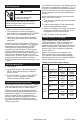
EN Maintenance Instructions WARNING Before working on engine or equipment, disable engine as follows: 1) Disconnect spark plug lead(s). 2) Disconnect negative (–) battery cable from battery. Accidental Starts can cause severe injury or death. Disconnect and ground spark plug lead(s) before servicing. Safety is an obligation of owner. Periodic inspection, adjustment and lubrication will keep your generator in safest and most efficient condition possible.
Oil Sentry™ (if equipped) Fuel Level This switch is designed to prevent engine from starting in a low oil or no oil condition. Oil Sentry™ may not shut down a running engine before damage occurs. WARNING Explosive Fuel can cause fires and severe burns. Fuel Recommendations Do not fill fuel tank while generator is hot or running. WARNING Explosive Fuel can cause fires and severe burns. Do not fill fuel tank while engine is hot or running.
Spark Plugs EN Air Cooling CAUTION WARNING Electrical Shock can cause injury. Hot Parts can cause severe burns. Do not touch wires while generator is running. Never operate generator in rain or snow. Never touch generator with wet hands or electrical shock may occur. When replace spark plug light (Z) goes on, press reset (AC) and follow maintenance instructions. Clean out spark plug recess. Remove spark plug (Q) and replace. 1. Check gap using wire feeler gauge.
GFCI Receptacle CAUTION Electrical Shock can cause injury. Do not touch wires while generator is running. Never operate generator in rain or snow. Never touch generator with wet hands or electrical shock may occur. To reduce chance of electrical shock: 1. Do not attempt to operate equipment if ground fault circuit interrupter (GFCI) RESET button pops out repeatedly during use. 2. Remember that only receptacles labeled GFCI have ground fault circuit interrupter protection.
Battery Charging Using DC Receptacle (if equipped) CAUTION Electrical Shock can cause injury. Do not touch wires while generator is running. Never operate generator in rain or snow. Never touch generator with wet hands or electrical shock may occur. NOTE: This section refers to charging 12V batteries in other equipment like motor vehicles or off-road vehicles. No jump-starting is possible.
Clean Generating Set 1. Remove all dust and debris from around exhaust. 2. Clean generating set, particularly alternator and engine air inlets and outlets, using a cloth and brush. 3. Check general condition of generating set and replace any faulty parts. Transporting Generator Before transporting generator, check that bolts are correctly tightened, close fuel valve (X) and disconnect starter battery (O). Generator should be transported in its normal operating position; never lay it on its side.
EN Troubleshooting Do not attempt to service or replace major engine components, or any items that require special timing or adjustment procedures. This work should be performed by a Kohler portable dealer.
Specifications Model PRO 3.7/ PRO 3.7 E PRO 5.2/ PRO 5.2 E PRO 7.5/ PRO 7.5 E Overall Dimensions (L x W x H) 24.3 in. (617 mm) 18.8 in. (478 mm) 19.2 in. (488 mm) Dry Weight 138 lbs. (63 kg)/ 154 lbs. (70 kg) AC Rated Power (120 Volts x (120 Volts x (120 Volts x 3000 25.0 Amps) 4500 37.5 Amps) 6300 52.5 Amps) Watt (240 Volts x Watt (240 Volts x Watt (240 Volts x 18.8 Amps) 26.3 Amps) 12.5 Amps) AC Maximum Power (120 Volts x (120 Volts x (120 Volts x 3700 30.8 Amps) 5200 43.3 Amps) 7500 62.
EN Accessory System Accessory kits available for models in table below which includes custom kits consisting of legs, handles, wheels, lifting kits — whatever you want, any way you want it. Accessory System Wheel Kit PRO 3.7/ PRO 5.2/ PRO 7.5 / 3.7 E 5.2 E 7.5 E GEN 5.0 WP 2.0 ● ● ● ● ● WP 3.0 ● TP 3.
NOTE: A clamping device or an assistant to hold assembly while installing kit will make process easier. Install Wheelbarrow Handle Kit Wheelbarrow Handle Kit Lift kit includes lift bar and mounting hardware. 1. Align lift bar holes under holes of frame. 2. While holding in this position, install screws. 3. Thread nuts to screws. Torque to 221 in. lb. (25 N·m). Install Hand Truck Handle Kit Hand Truck Handle Kit Wheelbarrow handle kit includes two wheelbarrow handles and mounting hardware. 1.
ESS PRO 3.7, PRO 3.7 E, PRO 5.2, PRO 5.2 E, PRO 7.5, PRO 7.5 E Manual del Usuario del Generador IMPORTANTE: Lea atentamente todas las instrucciones y precauciones de seguridad antes de poner el equipo en funcionamiento. Asegúrese de que el motor está parado y nivelado antes de realizar tareas de mantenimiento o reparación. Registre la información del producto con el fin de consultarla para realizar pedidos de piezas o para obtener la cobertura de la garantía.
Precauciones de seguridad PELIGRO: Un peligro que provoca la muerte, lesiones graves o daños materiales considerables. ADVERTENCIA: Un peligro que podría provocar la muerte, lesiones graves o daños materiales considerables. PRECAUCIÓN: Un peligro que podría provocar lesiones personales o daños materiales de poca gravedad. NOTA: Se utiliza para notificar al personal sobre información importante para la instalación, el funcionamiento o el mantenimiento.
Advertencia: la Propuesta 65 de California El escape de motor de este producto contiene sustancias químicas identificadas por el Estado de California como causantes de cáncer, defectos de nacimiento u otros daños genéticos. ESS Advertencia: la Propuesta 65 de California Este producto contiene sustancias químicas identificadas por el Estado de California como causantes de cáncer, defectos de nacimiento u otros daños genéticos.
A B E E E E E F V U I J C AE AC Y D G G H W T AD K Z AA AB N M O S L X Q P R A Interruptor de carga B Mantenimiento del protector C Tomacorriente eléctrico de 240/120V/30A D Tomacorriente eléctrico de 120V/30A E Protector de circuitos F Receptáculo de CC de 12V3 Interruptor de encendido/apagado/arranque Tapón de llenado de aceite/varilla de nivel G Receptáculo GFCI H Terminal de masa I M Q U Y AC 1 Tapón del tanque de Indicador del nivel de Ralentí automático3 J K
Lista de control previa al arranque 1. Asegúrese de que el generador esté al menos a 1 m (3,3 ft) del edificio o de cualquier otro equipo y no esté tapado con ningún material. 2. Consulte todas las etiquetas de advertencia antes de poner en marcha. 3. Compruebe el nivel de aceite por medio del tapón de llenado de aceite (N). Añada aceite si está bajo. No rellene por encima del límite. 4. Verifique el indicador de nivel de combustible (L). Añada combustible si está bajo.
Ángulo de funcionamiento No haga funcionar el motor si supera el ángulo máximo de funcionamiento, consulte la tabla de especificaciones. El motor puede dañarse como resultado de una lubricación insuficiente. Selección del cable Tipo de tomacorriente del generador Cuando el interruptor de ralentí automático (I) está en la posición OFF, el motor funciona al nivel nominal de rpm (3.600 rpm), haya o no una carga conectada.
Instrucciones de mantenimiento ADVERTENCIA Los arranques accidentales pueden provocar lesiones graves o la muerte. Antes de llevar a cabo trabajos de mantenimiento o reparación, desconecte y aísle el cable de la bujía. ESS Antes de realizar cualquier trabajo en el motor o en el equipo, desactive el motor como se indica a continuación: 1) Desconecte los cables de las bujías. 2) Desconecte el cable del polo negativo (-) de la batería. La seguridad es una obligación del propietario.
3. Vuelva a instalar el tapón de drenaje del aceite (M). Apriételo a 17,6 N·m (13 ft lb). 4. Llene de aceite nuevo el cárter hasta el punto de desbordamiento del cuello de llenado. 5. Vuelva a colocar el tapón/varilla de nivel/ llenado (N) y apriete firmemente. 6. Deseche el aceite usado en conformidad con las normativas locales. Nivel de combustible ADVERTENCIA La explosión del carburante puede provocar incendios y quemaduras graves.
6. Vuelva a instalar la cuba de sedimentos. 7. Abra la válvula del tanque de combustible (X). Refrigeración por aire ESS 8. Limpie cualquier rastro de combustible con un trapo limpio y revise que no haya fugas. ADVERTENCIA Las piezas calientes pueden causar quemaduras graves. Bujías No toque el generador durante el funcionamiento o inmediatamente después de pararse. PRECAUCIÓN Las descargas eléctricas pueden provocar lesiones. No toque los cables con el generador en funcionamiento.
Potencia máxima de CA Sobrecarga (capacidad del generador) La potencia máxima de CA es una potencia adicional producida momentáneamente por el generador para ayudar a poner en marcha dispositivos eléctricos que requieren una potencia superior a la potencia nominal del generador. Receptáculo GFCI PRECAUCIÓN Las descargas eléctricas pueden provocar lesiones. No toque los cables con el generador en funcionamiento.
Potencia del receptáculo del selector de voltaje Posición del Interruptor Potencia Disponible Tomacorriente PRO 3.7 eléctrico PRO 3.7 E 240V/120V/ 30A 25A @ 120V 30A @ 120V 25A @ 120V 30A @ 120V GFCI 20A @ 120V 20A @ 120V 240V/120V/ 30A 12.5A/ 240V 18.5A/ 240V 120V/30A 12.5A/ 120V 18.5A/ 120V GFCI 12.5A/ 120V 18.5A/ 120V Sólo 120V 120V/30A 120V/ 240V PRO 5.2 PRO 5.
Protector de circuitos de CC Transportación del generador NOTA: Reduzca la carga del dispositivo eléctrico conectado, por debajo de la salida nominal especificada del generador si el protector de circuitos de CC (E) se apaga. Si el protector de circuitos de CC (E) se vuelve a apagar, deje de usar el dispositivo inmediatamente y póngase en contacto con un distribuidor móvil de Kohler.
Localización de averías No intente reparar o cambiar componentes principales del motor o cualquier elemento que requiera unos procedimientos de ajuste o sincronización especiales. Este trabajo debe ser realizado por un distribuidor móvil de Kohler.
Especificaciones Modelo PRO 3.7/PRO 3.7 E PRO 5.2/PRO 5.2 E 617 mm (24,3 in.) 478 mm (18,8 in.) 488 mm (19,2 in.) Dimensiones generales (Largo x Ancho x Alto) 138 lbs. (63 kg)/ 154 lbs. (70 kg) Peso en seco PRO 7.5/PRO 7.5 E 670 mm (26,4 in.) 545 mm (21,5 in.) 535 mm (21,1 in.) 180 lbs. (82 kg)/ 201 lbs. (91 kg) 199 lbs. (90 kg)/ 220 lbs.
Instalación de kit de ruedas Instalación del kit de patas ESS Kit de ruedas Kit de patas Kit de ruedas (ruedas y patas) NOTA: Incline la unidad de manera que el tapón del tanque de combustible quede hacia arriba para asegurar que no haya fuga de combustible. NOTA: Un dispositivo o asistente de sujeción para sostener el ensamblaje mientras que el kit de instalación facilita el proceso. El kit de patas incluye 2 patas y herramienta de montaje.
Instalación del kit para manejo de cables Kit de cables Instalación de kit de manivelas manuales para camión Kit de manivelas manuales para camión El kit de manejo de cables incluye 2 montantes y herramienta de montaje. El kit de manejo de cables se puede instalar en cualquier lugar de la unidad, del mismo lado, no por toda la unidad. 1. Coloque los lados del montante juntos en el bastidor. 2. Coloque 3 tuercas en los orificios de 1 lado. 3.
PRO 3.7, PRO 3.7 E, PRO 5.2, PRO 5.2 E, PRO 7.5, PRO 7.5 E Manuel de l’utilisateur – Générateur IMPORTANT : Lisez toutes les consignes et précautions de sécurité avant d’utiliser le matériel. Le moteur doit être arrêté et de niveau avant d’exécuter tout travail de maintenance ou d’entretien. Enregistrez les informations concernant le produit pour référence lors de la commande de pièces ou de demande de couverture de garantie. Spécifications Numéro de série Date d’achat : 37 590 01 Rév. I KohlerPower.
Consignes de sécurité DANGER : Un danger pouvant entraîner la mort, de graves blessures ou des dommages matériels. AVERTISSEMENT : Un danger pouvant entraîner la mort, de graves blessures ou des dommages matériels. ATTENTION : Un danger pouvant entraîner des blessures légères ou des dommages matériels. REMARQUE : Cette mention est utilisée pour attirer l’attention sur des détails importants concernant l’installation, l’utilisation ou l’entretien.
Californie Proposition 65 Avertissement L’échappement de moteur émanant de ce produit comprend des agents chimiques qui, selon l’État de Californie, sont la cause de cancers, d’anomalies congénitales, ou d’autres lésions génésiques. FRC Californie Proposition 65 Avertissement Ce produit comprend des agents chimiques qui, selon l’État de Californie, sont la cause de cancers, d’anomalies congénitales ou d’autres lésions génésiques.
A B E E E E E F V U I J C AE D G G H W T AC Y AD K Z AA AB N M O S L X Q P R A Disjoncteur B Indicateur d’entretien C Prise électrique 240/120 V – 30 A D Prise électrique 120 V/30 A E Dispositif de protection du circuit F Prise 12 Vcc3 G Prise GFCI H Borne de masse I Ralenti automatique3 J Bouton On/Off/ Start (marche/arrêt/ démarrage) K Bouchon du réservoir de carburant L Témoin de niveau de carburant M Bouchon de vidange d’huile N Bouchon du goulot d’
Liste de vérification à utiliser avant le démarrage 1. Le générateur doit être à une distance de 1 m (3,3 pi) du bâtiment ou autre matériel et ne doit pas être recouvert. 2. Vérifiez toutes les étiquettes avant de commencer. 3. Vérifiez le niveau d’huile à l’aide du bouchon de remplissage d’huile (N). Ajoutez de l’huile si le niveau est bas. Ne remplissez pas trop le réservoir. 4. Vérifiez le témoin de niveau de carburant (L). Ajoutez du carburant si le niveau est bas.
Sélection de câble Type de prise de générateur mm2 AWG mm2 AWG 32 A AWG 16 A mm2 Section de câble recommandée 10 A 4 10 6 9 10 7 10 7 10 7 25 3 0à 50 m Longueur 51 à de câble 100 m utilisé 101 à 150 m1 10 7 16 5 35 2 Cette longueur de câble représente la longueur maximale autorisée. Elle ne doit en aucun cas être dépassée. 1 Méthode d’installation=câbles sur chemin ou tablette non percée/chute de tension autorisée=5 %/Conducteurs multipolaires/Câble type PVC 70 C (ex.
Consignes d’entretien AVERTISSEMENT Des démarrages accidentels peuvent causer des blessures graves voire mortelles. Débranchez le(s) câble(s) de bougie et mettez-le(s) à la masse avant l’entretien. FRC Arrêtez le moteur avant d’effectuer des travaux de réparation et d’entretien du moteur ou de l’équipement en suivant les consignes ci-dessous : 1) Débranchez le(s) câble(s) de bougie. 2) Débranchez le câble négatif (–) de batterie de la batterie. Le propriétaire est responsable de la sécurité.
Oil Sentry™ (le cas échéant) Niveau de carburant Ce commutateur est conçu pour éviter au moteur de démarrer s’il n’y a pas d’huile ou si le niveau est bas. Oil Sentry™ peut ne pas couper le moteur avant que les dommages ne se produisent. AVERTISSEMENT Carburant explosif pouvant causer des incendies et des brûlures graves. Recommandations relatives au carburant AVERTISSEMENT Carburant explosif pouvant causer des incendies et des brûlures graves.
Bougies Système de refroidissement par air ATTENTION AVERTISSEMENT Les chocs électriques peuvent causer des blessures. Les pièces chaudes peuvent causer de graves brûlures. Ne touchez pas aux fils pendant que le générateur tourne. Ne touchez pas au générateur pendant qu’il tourne ou si vous venez tout juste de l’arrêter. Ne laissez jamais tourner le générateur sous la pluie ou la neige. Ne touchez jamais le générateur avec les mains mouillées. Il y a risque de choc électrique.
Prise GFCI ATTENTION Les chocs électriques peuvent causer des blessures. Ne touchez pas aux fils pendant que le générateur tourne. Ne laissez jamais tourner le générateur sous la pluie ou la neige. Ne touchez jamais le générateur avec les mains mouillées. Il y a risque de choc électrique. Pour réduire les risques de choc électrique : 1.
Chargement de batterie utilisant la prise CC (si présent) ATTENTION Les chocs électriques peuvent causer des blessures. Ne touchez pas aux fils pendant que le générateur tourne. Ne laissez jamais tourner le générateur sous la pluie ou la neige. Ne touchez jamais le générateur avec les mains mouillées. Il y a risque de choc électrique. REMARQUE : Cette section fait référence aux batteries 12 V dans d’autres équipements comme les véhicules à moteur ou les véhicules tout-terrain.
Nettoyage du groupe électrogène 1. Éliminez toute la poussière et les débris autour de l’échappement. 2. Nettoyez le groupe électrogène, notamment les entrées et les sorties d’air de l’alternateur et du moteur, avec un chiffon et une brosse. 3. Vérifiez l’état général du groupe électrogène et remplacez les pièces défectueuses. Transport du générateur Avant de transporter le générateur, vérifiez le serrage des boulons, fermez le robinet de carburant (X) et débranchez la batterie de démarreur (O).
Recherche de pannes N’essayez pas de faire l’entretien ou de réparer les principaux composants du moteur, ou tout élément qui requiert un calage ou des procédures de réglage spéciaux. Ce travail doit être réalisé par un concessionnaire Kohler.
Spécifications Modèle Dimensions hors tout (L x l x h) Poids à sec PRO 3.7/PRO 3.7 E PRO 5.2/PRO 5.2 E 617 mm (24,3 po) 478 mm (18,8 po) 488 mm (19,2 po) 138 lbs (63 kg)/ 154 lbs (70 kg) PRO 7.5/PRO 7.
Système d’accessoires Les kits d’accessoires disponibles pour les modèles dans le tableau ci-dessous comprennent les kits personnalisés se composant de pattes, poignées, roues, kits de levage, ce que vous voulez, comme vous le voulez. Système d’accessoires PRO 3.7 / PRO 5.2 / PRO 7.5 / 3.7 E 5.2 E 7.5 E FRC GEN 5.0 WP 2.0 WP 3.0 TP 3.
REMARQUE : Un dispositif de serrage ou un assistant pendant l’installation du kit facilite le processus. Installation du kit de poignée de brouette Kit de poignée de brouette Le kit de levage comprend la barre de levage et le matériel de montage. 1. Alignez les trous de barre de levage sous les trous du cadre. 2. Tout en maintenant cette position, installez les vis. 3. Vissez les écrous sur les vis. Serrez au couple de 25 N·m (221 po-lb).