Operation Residential/Commercial Generator Sets Models: 14/20RESA 14/20RESAL Controllers: RDC2 DC2 TP-6804 1/15h
California Proposition 65 WARNING Engine exhaust from this product contains chemicals known to the State of California to cause cancer, birth defects, or other reproductive harm. Product Identification Information Product identification numbers determine service parts. Record the product identification numbers in the spaces below immediately after unpacking the products so that the numbers are readily available for future reference. Record field-installed kit numbers after installing the kits.
Table of Contents Product Identification Information . . . . . . . . . . . . . . . . . . . . . . . . . . . . . . . . . . . . . . . . . . . . . . . . . . . . . . . . . . . . . 2 Safety Precautions and Instructions . . . . . . . . . . . . . . . . . . . . . . . . . . . . . . . . . . . . . . . . . . . . . . . . . . . . . . . . . 7 Introduction . . . . . . . . . . . . . . . . . . . . . . . . . . . . . . . . . . . . . . . . . . . . . . . . . . . . . . . . . . . . . . . . . . . . . . . . . . . . . . .
Table of Contents, continued 3.5 3.6 Changing Settings . . . . . . . . . . . . . . . . . . . . . . . . . . . . . . . . . . . . . . . . . . . . . . . . . . . . . Setting the Exerciser . . . . . . . . . . . . . . . . . . . . . . . . . . . . . . . . . . . . . . . . . . . . . . . . . . . 3.6.1 Setting the Exerciser at Controller Power-up . . . . . . . . . . . . . . . . . . . . . . 3.6.2 Changing the Exercise Settings . . . . . . . . . . . . . . . . . . . . . . . . . . . . . . . . . . RDC2 Controller Menus . .
Table of Contents, continued 5.5 5.6 5.7 5.8 Cooling System . . . . . . . . . . . . . . . . . . . . . . . . . . . . . . . . . . . . . . . . . . . . . . . . . . . . . . . Exhaust System . . . . . . . . . . . . . . . . . . . . . . . . . . . . . . . . . . . . . . . . . . . . . . . . . . . . . . . Fuel Regulator Vent Tubes . . . . . . . . . . . . . . . . . . . . . . . . . . . . . . . . . . . . . . . . . . . . . . Battery . . . . . . . . . . . . . . . . . . . . . . . . . . . . . . . . . . . . . . . . . . . . .
Notes 6 TP-6804 1/15
Safety Precautions and Instructions IMPORTANT SAFETY INSTRUCTIONS. Electromechanical equipment, including generator sets, transfer switches, switchgear, and accessories, can cause bodily harm and pose life-threatening danger when improperly installed, operated, or maintained. To prevent accidents be aware of potential dangers and act safely. Read and follow all safety precautions and instructions. SAVE THESE INSTRUCTIONS.
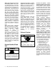
Battery gases. Explosion can cause severe injury or death. Battery gases can cause an explosion. Do not smoke or permit flames or sparks to occur near a battery at any time, particularly when it is charging. Do not dispose of a battery in a fire. To prevent burns and sparks that could cause an explosion, avoid touching the battery terminals with tools or other metal objects. Remove all jewelry before servicing the equipment.
Fuel System WARNING Hazardous Noise CAUTION Explosive fuel vapors. Can cause severe injury or death. Hazardous noise. Can cause hearing loss. Use extreme care when handling, storing, and using fuels. Never operate the generator set without a muffler or with a faulty exhaust system. The fuel system. Explosive fuel vapors can cause severe injury or death. Vaporized fuels are highly explosive. Use extreme care when handling and storing fuels.
Welding on the generator set. Can cause severe electrical equipment damage. Before welding on the generator set perform the following steps: (1) Remove the battery cables, negative (--) lead first. (2) Disconnect all engine electronic control module (ECM) connectors. (3) Disconnect all generator set controller and voltage regulator circuit board connectors. (4) Disconnect the engine batterycharging alternator connections. (5) Attach the weld ground connection close to the weld location.
Introduction This manual provides operation and maintenance instructions for residential/commercial model 14/20RESA and 14/20RESAL generator sets equipped with Kohler RDC2 or DC2 generator set/transfer switch controllers. See Figure 1. The RDC2 and DC2 controllers control the generator set and the optional Model RXT transfer switch. Have the generator set installed by an authorized distributor/dealer or service technician. Refer to TP-6803, Installation Manual, for installation instructions.
Nameplate Refer to the certification label for engine displacement. The following illustration shows a typical generator set nameplate. Copy the model, serial, and specification numbers from the nameplate into the spaces provided in the product information section on the inside front cover of this manual. See the service views in Section 1.8 for the nameplate location. The exhaust emission control system for the CH740 engines (14RESA/RESAL) is EM for U.S. EPA, California, and Europe.
Service Assistance For professional advice on generator set power requirements and conscientious service, please contact your nearest Kohler distributor or dealer. D Consult the Yellow Pages under the heading Generators—Electric. D Visit the Kohler Power Systems website at KOHLERPower.com. D Look at the labels and stickers on your Kohler product or review the appropriate literature or documents included with the product. D Call toll free in the US and Canada 1-800-544-2444.
Notes 14 Service Assistance TP-6804 1/15
Section 1 Descriptions and Service Views 1.1 Introduction The generator set specification sheets provide specific generator and engine information. Refer to the spec sheet for data not supplied in this manual. Consult the generator set service manual, engine operation manual, and engine service manual for additional specifications. Obtain copies of the latest spec sheets, manuals, diagrams, and drawings from your local distributor/ dealer. 1.
D Programmable exerciser can be set to start automatically on any future day and time, and run every week or every two weeks D Exercise modes d Unloaded weekly exercise with complete system diagnostics d Unloaded full-speed exercise d Loaded full-speed exercise (Model RXT ATS required) D Front-access mini USB connector for Kohlerr RDC2 (RESA) DC2 (RESAL) SiteTecht connection Figure 1-2 Revised (red--board) Controllers D Integral Ethernet connector for the Kohlerr OnCuer RDC2 Controller Features
D Programmable displays Interface Module (PIM) status d Input status (active/inactive) d Output status (active/inactive) D Load control module (LCM) menus DC2 Controller Features OFF, AUTO, RUN, and D LED indicators for OFF, AUTO, and RUN modes D LCD display: d Two lines x 16 characters per line d Backlit display with adjustable contrast for excellent visibility D Scrolling system status display d Generator set status d Voltage and frequency d Engine temperature d Oil pressure d Battery voltage d Eng
1.7 Accessories The following optional accessories are offered for the RESAand RESAL generator sets. 1.7.1 Carburetor Heater An optional carburetor heater is recommended for improved cold starting in locations where the ambient temperature drops below 0_C (32_F). The carburetor heater prevents condensation and carburetor icing. The heater requires a continuous source of AC power. See the generator set Installation manual for more information. 1.7.
1.8 Service Views 2 5 1 8 7 6 3 4 10 11 9 12 13 14 15 26 16 BACK DETAIL 17 18 19 25 24 AIR INTAKE SIDE PANEL REMOVED TO SHOW DETAIL 1. 2. 3. 4. 5. 6. 7. 8. 9. 10. 11. 12. 13. 14. 15. 27 29 23 22 21 20 Hinged inner cover Hinged roof Air intake Lock Locking tool, provided with generator set Exhaust outlet Oil check (dipstick) Oil fill Lifting holes Muffler Air cleaner Oil filter Line circuit breaker USB connector (for firmware updates) RDC2 or DC2 controller 28 ADV-8424 16. 17. 18. 19.
Notes 20 Section 1 Descriptions and Service Views TP-6804 1/15
Section 2 Generator Set Operation 2.1 Prestart Checklist To ensure continued satisfactory operation, perform the following checks or inspections before or at each startup, as designated, and at the intervals specified in the service schedule. In addition, some checks require verification after the unit starts. Air Cleaner. Check for a clean and installed air cleaner element to prevent unfiltered air from entering the engine. Air Inlets. Check for clean and unobstructed air inlets. Battery.
2.3.1 Local Starting and Stopping Start: Press the RUN button to immediately start the generator set. Stop: Press the OFF button. The engine stops. Run the generator set with no load for at least 2 minutes to ensure adequate engine cooldown. 2.3.2 Automatic Operation An automatic transfer switch monitors the utility power and signals the generator set to start when utility power is lost. The ATS then transfers the load to the generator set.
Press the AUTO button to put the controller into automatic mode. 2.4.2 Automatic Start An unloaded exercise runs the generator set without signalling the transfer switch to transfer the electrical load from the utility source to the generator set. The Unloaded Cycle exercise with diagnostics is the recommended exercise mode and is the default exercise setting. Automatic Stop The engine start contacts on the ATS open to signal the generator set to stop. 2.
the controller detects low battery voltage, the condition is indicated on the display. 2.4.4 J1939, RBUS, Ethernet, and USB are monitored for messages indicating that the controller and wiring are reliable. A loaded exercise starts the generator set, ramps up to full speed, and then transfers the electrical load from the utility source to the generator set. After 20 minutes, the load is transferred back to the utility source.
2.5 Faults 2.5.4 The RDC2 or DC2 controller displays fault messages for generator set warnings and shutdowns. Selected fault messages are shown in Figure 2-3. Contact an authorized distributor/dealer for service, if necessary. 2.5.1 Warnings The controller displays a fault message but the generator set does not shut down on a warning. The controller resets automatically after a warning condition is corrected. 2.5.
Fault Message AC Sens Loss Warning (W) or Shutdown (SD) Condition W (1 sec.) SD (3 sec.) * Check AC sensing lost. In Auto mode, generator output Contact an authorized AC sensing is lost. Detection begins10 seconds distributor/dealer for service. after crank disconnect. Warning: after 1 second if no output detected after crank disconnect. Shutdown: after 3 seconds if voltage was present and then lost. Accy PwrOver Warning W Accessory Power Overload.
Fault Frequency Low Warning (W) or Shutdown (SD) Condition SD * Governed frequency falls below 90% of the system frequency setting for more than 10 seconds, or 1 Hz below the system frequency setting for more than 60 seconds. Function becomes active 10 seconds after engine start (10 second inhibit). Check Reduce the load and restart the generator set. Contact an authorized distributor/dealer for service. Lo Crank Vlt W Low cranking voltage.
2.5.5 Faults Related to Paralleling If the PowerSync Automatic Paralleling Module (APM) is used with two 14RESA or two 20RESA generator sets, additional faults and events related to the paralleling system may be displayed on the controller and/or in OnCue Plus. This section lists those faults and events. See TT-1596, provided with the APM, for additional paralleling information. Note: Contact an authorized distributor or dealer for paralleling system installation, startup, troubleshooting, or service.
Fault Text Description Possible Causes * ErraticSig The power metering on this controller gives a signal that is not consistent with the system configuration. Reversing the power direction does not resolve the problem. Bad wiring to the CT. The Automatic Paralleling Module has stopped communicating on RBUS. (An APM was detected on the RBUS network but is no longer communicating.) APM is unplugged. LossOfComAPM Too much tension on wires from the CT to the controller.
Notes 30 Section 2 Generator Set Operation TP-6804 1/15
Section 3 RDC2 Controller Operation 3.1 RDC2 Generator Set/Transfer Switch Controller Model RESA generator sets are equipped with the RDC2 generator set/transfer switch controller. See Figure 3-1 for controller illustrations. The operation is the same for the original and revised controllers. 1 Model RESAL generator sets are equipped with the DC2 controller. See Section 4 for DC2 controller operation information.
3.2.1 Controller Keypad 3.2.2 LED Indicators The RUN, OFF, and AUTO buttons control the generator set as described in Figure 3-3. LEDs above the RUN, OFF, and AUTO buttons indicate the mode of operation as shown in Figure 3-4. Use the Select, Up arrow, and Down arrow buttons to navigate through the menus and change settings, if necessary. See Section 2.3 for operation instructions.
3.2.3 LCD Display The controller is equipped with a two-line x 16 character backlit digital display with adjustable contrast. When the generator is running, the controller automatically scrolls through the displays shown in Figure 3-5. When the system is in AUTO, the screens shown in Figure 3-6 are displayed. When a fault or warning condition exists, the controller will show the corresponding message. See Section 2.5 for more information about faults.
3.3 Controller Power The RDC2 controller is powered by the generator set engine starting battery and the built-in battery charger. Note: To disconnect controller power, disconnect the utility power to the generator set and disconnect the battery. If controller power is disconnected and reconnected, you will be prompted to set the language, time, date, and exerciser. The first setting will flash. Press the Up and Down arrow buttons to change the setting.
Changing Settings on the RDC2 Controller 1. Press the Select button to enter the main menu. Press: Display: Overview ----> 1.2 h Press: 2. Press the down arrow button until the desired menu is displayed. See Figure 3-9. Date and Time are used for this example. Press: Display: Date ----> Display: Date: 05Dec2011 4. To change the date and time settings, press the Select button again. The year will flash.
3.6 Setting the Exerciser Set the exerciser to automatically run the generator set for 20 minutes every week or every two weeks. 3.6.1 Setting the Exerciser at Controller Power-up When battery power is connected to the controller, you will be prompted to set the language, date and time, and then to set the exerciser. The first setting will flash. Press the Up and Down arrow buttons to change the setting. Press Select to save the setting and move on to the next. See Section 3.
Genset System ----> System Freq: XX.X Hz System Phase System Volt System Battery Fuel Type HOLD: Next Exercise * Next Exercise HR:MN PM MM/DD/YY HR:MN PM MM/DD/YY HOLD: Exercise Mode: Exercise Mode: Loaded Unloaded Cycle/Unloaded Full/ Loaded Full HOLD: Exercise Freq: Exercise Freq: Weekly Weekly/Bi-Weekly Language: Contrast: 50 <---- Return * If the exerciser has not been set, No Exercise Sch will be displayed.
3.7 RDC2 Controller Menus Controller menus display power system information, including status information for the engine, generator, and optional RBUS accessories, exercise settings, and event history. Some menus allow changes to the controller settings. Status information, including the engine runtime, cannot be changed by the operator. Diagrams in the following sections show how to navigate through the menus. The diagrams show sample settings. Settings for your application may vary.
Status Displays Press the Up and Down arrow buttons to move between menus. Press OFF or AUTO to exit the menus. Overview ----> 1.2 h Engine ----> Metering ATS ----> Configuration * Generator----> Metering Date ----> and Time Genset ----> Information Network ----> Information Genset ----> Run Time PIM ----> Status [ Genset System ----> Load ----> Control ] ATS Status ----> Event Log * ATS Configuration appears only if a Model RXT transfer switch is connected.
3.9 Overview Menu Overview ----> 1.2 h 3.10 Engine Metering Menu The engine metering menu displays engine status information as shown in Figure 3-11. This menu displays status information only. No settings can be changed from this menu. Active Alert (if any) Engine ----> Metering Genset Status Standby Eng Speed: 3600 RPM Oil Pressure: Switch: OK Voltage: 240V Freq: 60.0Hz Oil Temp: Engine: 72F Oil Pressure: OK Battery: Battery 72.0 F 12.0 V 12.0V <---- Return Engine Runtime: 24.
3.11 Generator Metering Menu Voltage Calibration The generator metering menu displays the generator voltage and frequency. See Figure 3-12. DANGER Hazardous voltage. Will cause severe injury or death. This equipment must be installed and serviced by qualified electrical personnel. The voltage calibration mode can be entered from the Generator Metering menu. Contact a Kohler-authorized distributor/dealerdealer for service.
3.12 Generator Set Information Menu 3.13 Genset Run Time Menu The generator set model number and serial numbers are displayed. No changes are allowed from this menu. Model and serial numbers are factory set and should not require changes in the field, except in the event that the controller is being replaced. A personal computer running Kohler SiteTech software is required to enter the generator set model number and serial numbers on a replacement controller.
3.14 Genset System Menu The genset system menu displays the system information shown in Figure 3-15. Generator sets are factory set and should not require changes to the system settings in the field. A Kohler authorized distributor or dealer can adjust these settings, if necessary. If the generator set is reconnected to a different voltage or the system settings require adjustment for some other reason, see Section 3.5 for instructions to enable editing and change the system settings.
3.15 ATS Status Menu ATS menus appear if a Model RXT transfer switch is connected to the generator set. If no transfer switch is connected, or another model ATS is connected to the engine start connections, Remote ATS is displayed on the ATS Status screen. ATS ----> Status The ATS Status menu displays Model RXT transfer switch and source information. The voltage shown in these menus can be calibrated. Follow the safety precautions at the beginning of this manuals.
3.16 ATS Configuration Menu Note: The ATS Configuration menu appears only if a Model RXT transfer switch is connected. Use the ATS Configuration submenu to check the Model RXT transfer switch system settings and time delays, and change the settings, if necessary. ATS ----> Configuration Normal Freq: 60 Hz Normal Voltage: 240 V Changing ATS Configuration Settings To enable editing, press the select button. The value flashes to indicate that it can be changed.
3.17 Date and Time Menu Date and Time The date and time will typically be set at controller power--up. To change the date, time, or time format (12 hour or 24 hour), use the Date and Time menu. See Figure 3-18. Date: 02Dec2011 Time: 3.18 Networking Information Menus 12:34pm Use the networking menus to view and adjust communication settings for systems with remote RBUS devices such as a PIM or LCM, and for systems that use the Kohler OnCuer Plus Generator Management System.
3.18.1 Networking Status Submenu The Networking Status submenu contains settings for OnCuer. Changes to these settings are not typically required. To enable or disable DHCP and change the IP settings, go to the Networking Configuration menu. See Section 3.18.2. If DHCP is enabled, IP parameters are not displayed. If DHCP is disabled (i.e., if a static IP address is used), the IP parameters are displayed.
3.18.2 Networking Configuration Submenu (OnCue Password) reset after the OnCue Plus system has been set up, the connection will be lost. Disconnect the battery power to the controller, wait a minute, then reconnect power. The Networking Configuration menu includes settings used for communication with the Kohler OnCuer Plus Generator Management System. DHCP Submenu Password Note: Use the OnCue password shown on the controller display for OnCue or OnCue Plus applications.
Networking----> Information Networking----> Status HOLD Networking Configuration Reset OnCue Password? No Reset OnCue Password UP arrow for YES, Down arrow for NO. RBUS ----> Information Reset OnCue Password? Yes Press Select to enter YES or NO as displayed. New password is displayed for approximately 10 seconds. S/N: 1234567 New PW: 12345 HOLD DHCP: Enabled DHCP: Disabled UP arrow to enable, Down arrow to disable. IP Address: 123.456.789.123 Subnet Mask: 123.456.789.123 Gateway: 123.456.789.
3.18.3 RBUS Information D Model RXT transfer switch The RBUS Information menu contains settings for remote modules that communicate with the RDC2 controller using RBUS protocol. This includes the following optional modules: D Programmable Interface Module (PIM) Networking----> Information D Load Control Module (LCM) or load shed kit Networking----> Status Networking----> Configuration RBUS ----> Information Modules Connected: 2 <---- Return Remote ----> Devices RD See Figure 3-23.
3.18.4 Remote Devices Submenu Check the status of remote devices communicating through RBUS. Device types can include: The serial numbers for the PIM, LCM, and load shed kit are printed on the circuit boards inside the enclosures. D Model RXT ATS D Programmable Interface Module (PIM) D Load Control Module (LCM) or load shed kit From Figure 3-22: Remote ----> Devices S/N: XXXXXXXXX <<*DeviceType*>> S/N: XXXXXXXXX <<*DeviceType*>> <---- Return Module Status: Connected Comm. Errors: 12345 Comm.
3.19 Programmable Interface Module (PIM) Status Menu The PIM status menu displays the status of inputs and outputs connected to the programmable interface module (PIM). this menu appears only if a PIM is connected. This is a status display menu only. Input and output settings cannot be changed from the RDC2 controller’s user interface. PIM Status: PIM 1 ----> <---- Return A personal computer running Kohler SiteTecht software is required to change the input and output settings.
3.20 Load Control Menus The Load Control menu displays the status of the Load Control Module (LCM) or load shed kit inputs and outputs, and allows a test of the load control output relays. This menu appears only if an LCM, load shed kit, or Model RXT transfer switch with the combined interface/load management board is connected. Load ----> Control Generator Current: Generator current is displayed as a percent of the maximum generator capacity.
3.21 Event Log The event log displays up to 1000 controller faults and notices, starting with the most recent event. Events are numbered 1--1000, with 1 being the most recent. Each event is displayed with the date and time of the event, the number of the event, a code to indicate whether the event was a warning ( W ), shutdown (S), or informational notice ( I), the engine hours at the time of the event, and the event description.
Section 4 DC2 Controller Operation 4.1 DC2 Generator Set/ Transfer Switch Controller Model RESAL generator sets are equipped with the DC2 generator set/transfer switch controller. 1 Model RESA generator sets are equipped with the RDC2 generator set/transfer switch controller. See Section 3 for RDC2 controller operation information.
4.2.1 Controller Keypad 4.2.2 The RUN, OFF, and AUTO buttons control the generator set as described in Figure 4-3. LED Indicators LEDs above the RUN, OFF, and AUTO buttons indicate the mode of operation as shown in Figure 4-4. Use the EXERCISE button to set the exerciser on the DC2 controller. See Section 4.5 for instructions to set the exerciser. Note: A personal computer (laptop) with Kohlerr SiteTecht software is required for changing settings on the DC2 controller.
4.2.3 LCD Display The controller is equipped with a two-line x 16 character backlit digital display with adjustable contrast. When the generator set is running, the messages shown in Figure 4-5 are displayed. When the system is in AUTO, the LCD display steps through the status messages shown in Figure 4-6. When a fault or warning condition exists, the controller will show the corresponding message. See Section 2.5 for more information on fault and warning messages.
4.5 Exercise 4.5.3 The DC2 controller can be set to automatically run the generator set at the same time and day each week. Exercising the generator set weekly is required to keep the engine and alternator in good operating condition. To reset the exerciser to run at a different day and/or time, follow the procedure in Section 4.5.2 to enter the new exerciser settings. The old settings will be replaced by the new time and day.
4.7 Maintenance Timer 4.8 OnCue Password The maintenance timer keeps track of the time until the next recommended maintenance according to the maintenance schedule for the 14RESAL or 20RESAL generator set. Reset the maintenance timer after changing the oil and performing the other maintenance tasks recommended in Section 5. For the initial OnCuer Plus setup, you will be required to reset the OnCue password on the DC2 controller, and then enter it into the OnCue Plus application.
Notes 60 Section 4 DC2 Controller Operation TP-6804 1/15
Section 5 Scheduled Maintenance WARNING Accidental starting. Can cause severe injury or death. Disconnect the battery cables before working on the generator set. Remove the negative (--) lead first when disconnecting the battery. Reconnect the negative (--) lead last when reconnecting the battery. Disabling the generator set. Accidental starting can cause severe injury or death.
5.1.1 Service Schedule, 14RESA/RESAL Models System Component or Procedure Fuel See Section Procedure Visually Inspect Check Change Clean Test Flexible lines and connections X Main tank supply level Quarterly X Fuel piping Lubrication R Frequency Weekly X Yearly 5.2 Oil level X Crankcase breather hose 8 hours or before use X X Yearly or 500 hours Change oil X Yearly or 100 hours Replace filter X Yearly or 200 hours Cooling 5.
5.1.2 Service Schedule, 20RESA/RESAL Models Procedure System Component or Procedure Fuel See Section Flexible lines and connections Visually Inspect Check Change X Main tank supply level Test R X Fuel regulator vent tubes, if equipped X Frequency Quarterly X Fuel piping Lubrication Clean Weekly Yearly X Yearly 5.
5.2 Lubrication System 5.2.2 See the service schedules in Section 5.1 for oil change and oil filter replacement intervals. See the service views in Section 1.8 for the oil drain, oil check, oil fill, and oil filter locations. The generator set is shipped with oil. Before operating the generator set, check the engine oil in the crankcase. WARNING Accidental starting. Can cause severe injury or death. Oil Check To check the oil level, shut down the generator set and wait several minutes.
5.2.4 Oil Change Procedure Note: Dispose of all waste materials (engine oil, fuel, filter, etc.) in an environmentally safe manner. Drain the oil while it is still warm. 1. Drain the oil. a. Press the OFF button on the generator set controller. b. Disconnect the utility power to the generator set. c. Disconnect the generator set engine starting battery, negative (--) lead first. d. Remove the housing side panel. e. Clean the area around the dipstick and oil fill cap. f.
5.2.5 Resetting the Maintenance Timer 14/20RESA (RDC2): 5.3 Spark Plugs WARNING 1. From the Overview menu, step down to the Genset Run Time menu. 2. Press the Select button and then step down to the Next Maintenance screen. 3. Press the Select button. 4. Press the Up arrow button so that “Reset Maint Timer? Yes” is displayed. 5. Press the Select button. After about two minutes, the new maintenance interval and date are displayed. 14/20RESAL (DC2): 1.
Generator Set Model 14RESA/RESAL 5.4 Air Cleaner Service Spark Plug Gap 0.76 mm (0.030 in.) WARNING Figure 5-4 Spark Plug Gap Fire. Can cause severe injury or death. Do not smoke or permit flames or sparks near fuels or the fuel system. 1--514 Figure 5-5 Checking the Spark Plug Gap Servicing the air cleaner. A sudden backfire can cause severe injury or death. Do not operate the generator set with the air cleaner removed. 5.4.
Air Cleaner Service 5.4.2 Air Cleaner, 20RESA/RESAL Models Use the following procedure to replace the paper element at the intervals specified in the service schedule. Replace the paper element more often under extremely dusty or dirty conditions. The engine is equipped with a replaceable, high density paper air cleaner element. See Figure 5-8. 1. Press the OFF button on the generator set controller. 1 2. Disconnect the utility power to the generator set. 2 3.
Air Cleaner Service 5.6 Exhaust System Replace the paper element at the intervals indicated in the service schedule. See Section 5.1.2 for the service schedule. See Figure 5-8 for the air cleaner components. 1. Loosen the two cover retaining knobs and remove the cover. 2. Remove the paper element. 3. Do not wash the paper element or use pressurized air, as this will damage the element. Replace a dirty, bent, or damaged element.
5.8 Battery WARNING Sulfuric acid in batteries. Can cause severe injury or death. Refer to this section for general battery information and maintenance. Also consult the battery manufacturer’s instructions for battery maintenance. All generator set models use a negative ground with a 12-volt engine electrical system. Consult the generator set nameplate for the engine electrical system voltage. Consult the generator spec sheet for battery capacity recommendations for replacement purposes.
5.8.3 Checking Specific Gravity Use a battery hydrometer to check the specific gravity of the electrolyte in each battery cell. While holding the hydrometer vertically, read the number on the glass bulb at the top of the electrolyte level or the number adjacent to the pointer. If the hydrometer used does not have a correction table, use the correction factors in Figure 5-13. Determine specific gravity and electrolyte temperature of battery cells.
5.9 Storage Procedure Perform the following storage procedure before removing the generator set from service for three months or longer. Follow the engine manufacturer’s recommendations for storage, if available. Note: Run the generator set monthly whenever possible. 5.9.1 Lubricating System 1. Operate the generator set until it reaches operating temperature, or about 15 minutes. 2. Stop the generator set. 3. While the engine is still warm, drain the engine lubrication oil from the engine crankcase. 4.
Section 6 Troubleshooting 6.1 Introduction Use the troubleshooting charts in this section to diagnose and correct common problems. First check for simple causes such as a dead engine starting battery, loose connections, or an open circuit breaker. The charts include a list of common problems, possible causes of the problem, and recommended corrective actions. If the procedures in this manual do not explain how to correct the problem, contact an authorized distributor/dealer.
1 1 1. Alternate mini-breaker location (access through air intake area) Figure 6-3 Auxiliary Winding Mini-Breaker Location GM90304 1.
6.5 Troubleshooting Figure 6-4 contains generator set troubleshooting, diagnostic, and repair information. Check for loose connections before replacing parts. Problem Possible Cause Corrective Action Controller display backlight is off. Backlight turns off after about 1 minute with no activity. Backlight will turn on when a button is pressed or the generator set starts. Controller display is off. Low or no battery voltage. Check connections. Check generator set battery. See Figure 6-4.
Notes 76 Section 6 Troubleshooting TP-6804 1/15
Appendix A Abbreviations The following list contains abbreviations that may appear in this publication. A, amp ABDC AC A/D ADC adj. ADV Ah AHWT AISI ALOP alt. Al ANSI AO APDC API approx. APU AQMD AR AS ASE ASME assy. ASTM ATDC ATS auto. aux. avg. AVR AWG AWM bat. BBDC BC BCA BCI BDC BHP blk. blk. htr. BMEP bps br. BTDC Btu Btu/min. C cal. CAN CARB CAT5 CB CC cc CCA ccw. CEC cert.
kg/cm2 kilograms per square centimeter kgm kilogram-meter kg/m3 kilograms per cubic meter kHz kilohertz kJ kilojoule km kilometer kOhm, k kilo-ohm kPa kilopascal kph kilometers per hour kV kilovolt kVA kilovolt ampere kVAR kilovolt ampere reactive kW kilowatt kWh kilowatt-hour kWm kilowatt mechanical kWth kilowatt-thermal L liter LAN local area network L x W x H length by width by height lb.
KOHLER CO. Kohler, Wisconsin 53044 Phone 920-457-4441, Fax 920-459-1646 Kohler Power Systems Asia Pacific Headquarters 7 Jurong Pier Road Singapore 619159 Phone (65) 6264-6422, Fax (65) 6264-6455 TP-6804 1/15h E 2011, 2012, 2013, 2014, 2015 by Kohler Co. All rights reserved. For the nearest KOHLER authorized installation, service, and sales dealer in the US and Canada: Call 1-800-544-2444 or visit KOHLERPower.