
Installation Guide


TT-1596 3/15 5
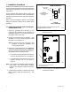
Programmable I/O
(optional)
OnCue
Plus
Internet
Automatic Paralleling Module (APM)
tt1596
RXT ATS
RXT
LCM or
load shed kit
PIM
Load Control
(required
] )
Distribution Panel
(Breakers)
Alternator
RDC2
Alternator
RDC2
CT
Utility
Communication cable (RBUS)
Network
connection
[
Voltage
sensing
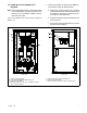
See wiring diagrams in Figure 33 and
Figure 34 for connection details.
RBUS
Emergency
Load
Load
Leads
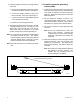
* Route all wiring in conduit. Route low-voltage communication leads in separate conduit from the load leads.
[ Connect both generator sets to the Internet through the customer’s Ethernet router/modem.
] Load control is required if one generator set cannot support the maximum total load.
Conduit *
Voltage sensing
Load leads
Network
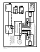
LEGEND
Load
Leads
Voltage
sensing
CT
RBUS
RBUS
Note: The APM must be
connected directly to the
generator set as shown.
Other accessories such as
the LCM and PIM must be
connected after the APM.
Figure 7 Block Diagram for Paralleling System Components and Connections