
Installation Guide


TT-1596 3/15 9
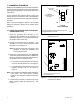
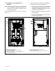
13. See Figure 9 and Figure 12. Carefully remove the
knockouts for the circuit breakers in the inner cover
of the enclosure:
a. Remove the larger portion on the left side of
each knockout for the 70 amp b reakers
(14RESA) OR
b. Remove both portions of the knockout for the
100 amp breakers (20RESA/20RESB).
1
GM85144
1. Remove only this portion for 70 amp breakers
2. Remove both portions for 100 amp breakers
2
Figure 12 Circuit Breaker Knockouts
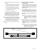
14. The decals shown in Figure 13 are provided in the
literature bag with the APM. Attach the
GENERATOR 1 and GENERATOR 2 decals
above the circuit breakers as shown in Figure 9.
15. Attach the Service Disconnect decals to the
outside of the inner cover near the openings for the
circuit breakers. Be sure to correctly label the
breakers for Generator 1 and Generator 2. See
Figure 13 and Figure 9.
16. Close the circuit breakers between the APM and
the generator sets.
The inner door for the APM enclosure will be installed
later.
GM85148
Figure 13 Decals provided with APM
1.4 Install the Model R XT transfer switch.
Note: Only one transfer switch can be used.
17. Install the ATS according to the installation
instructions and dimension drawings in the transfer
switch Installation Manual.
18. Do not connect the emergency source wiring or the
RBUS connections until instructed later in this
procedure.
1.5 Install the LCM or load shed kit and
optional PIM, if used.
Note: One PIM and one LCM or load shed kit can
be used. Multiple PIMs, LCMs, or load shed
kits cannot be connected.
19. Follow the installation instructions provided with
PIM and LCM or load shed kit(s).
Note: Connect sufficient non-critical loads to the
LCM or load shed kit so that one generator
set can support the remaining load, if
necessary.
Note: Do not install the CT provided with the LCM
or load shed kit. That CT is not needed, as
the generator controllers each have built-in
metering with the locally mounted CT that
was installed in Section 1.1.