
RDT Transfer Switch Manual


TP-6345 9/1318 Section 2 Installation
tp6345
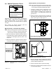
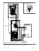
Main Distribution Panel (Normal Source)
Generator Set
(Emergency Source)
NL2
GRD *
N*
EL1
EL2
2-Pole
Feeder Breaker
3
4
Transfer Switch
with Load Center
(100 amp model shown)
L0 *
GRD *
* Connect according to NEC and local codes.
Engine
Start
N*
NL1
See Detail A.
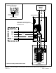
Engine Start, 3, 4
Load Control,
1, 2 (optional)
Detail A, Engine Start Leads to
ATS Main Logic Board
Common Fault,
5, 6 (optional)
Figure 2-8 Connection Diagram, Load Center Models, Essential Loads Configuration