
RDT Transfer Switch Manual


TP-6345 9/1334 Section 4 Accessories
7
GM39650
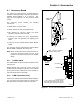
1. Engine cooldown time delay adjust SW1
2. Engine start time delay adjust SW2
3. Normal to emergency time delay adjust SW3
4. Emergency to normal time delay adjust SW4
5. Exercise run time adjust SW5
6. DIP switches SW6
7. Input/output connector P9 (black)
8. EAM connection P13
1
2
3
4
5
6
8
Figure 4-2 Accessory Board Component Locations
4.1.3 Inputs and Outputs
(Connector P9)
A remote test switch and an external exerciser can be
connected to the black 6-pin connector P9 on the
accessory board. See Figure 4-2 and Figure 4-3. P9
also includes a generator set supplying load output
connection.
Note: The ATS main logic board has a similar green
6-pin connector. Do not interchange the black
and green mating connectors.
Connections. Connect input and output leads to
connector P9. Refer to the label on the enclosure cover
or Figure 4-3 for the connections. Use #12--24 AWG
wire and tighten the connections to 0.5 Nm (4.4 in. lb.).
Remote Test Input. Connect a remote switch to this
input for remote starting and stopping of a loaded test.
DIP switch 3 affects the operation of this switch. See
Section 4.1.5, Accessory Board DIP Switches, and
Section 4.2, External Alarm Module.
Generator Set Suppling Load Output. This output
provides a closed contact to indicate that the generator
set is supplying the load when the transfer switch is in
the Emergency position and the GEN source is
available. Connect to customer-supplied equipment.
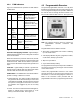
Remote Exercise Input. Connect the optional
Programmable Exerciser to this input to allow
scheduling of additional loaded or unloaded generator
set exercise runs. DIP switch 2 affects the operation of
this input. See Section 4.1.5, Accessory Board DIP
Switches.
See Section 4.3 and TT-1403, Programmable Exerciser
Instructions, for more information about the
programmable exerciser.
Note: Always replace the cover before energizing the
transfer switch controls.
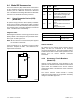
Function
Terminals,
Connector P9
Generator set supplying load output
Contact rated 10 amps @ 120VAC
1--2
Remote exercise input 3--4
Remote test input 5--6
Figure 4-3 Accessory Board Inputs and Outputs
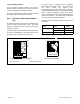
4.1.4 Time Delay Adjustment Switches
The 10-position rotary switches allow adjustment of the
time delays shown in Figure 4-4. Use a small
screwdriver or other small tool to increase or decrease
the time delays within the range shown in the table. The
rotary switch positions range from 1 to 10, with
position 10 labeled 0 (zero).
The factory settings are the same as the controller time
delays without the optional accessory board.
Time Delay
Factory Setting
Adjustment with
Accessory Board
Setting Switch Position (1--10[0]) Range Increment
Engine Cooldown 5 minutes 5 1--10 minutes 1 minute
Engine Start 3 seconds 3 1--10 seconds 1 second
Transfer from Normal to Emergency 3 seconds 3 1--10 seconds 1 second
Retransfer from Emergency to Normal 15 minutes 5 3--30 minutes 3 minutes
Exercise Run Time 20 minutes 4 5--50 minutes 5 minutes
Figure 4-4 Accessory Board Time Delay Adjustments