
RDT Transfer Switch Manual


TP-6345 9/13 47Section 6 Scheduled Maintenance
6.5 Surge Protective Device (SPD)
Replacement
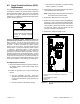
The green indicator light goes out if the SPD capability is
exceeded or if there is an internal safety component
failure in the SPD module. See Figure 4-10. Replace
the module if the green indicator is off and the red
indicator is on. Follow the replacement procedure in this
section and see Figure 6-1.
Hazardous voltage.
Will cause severe injury or death.
This equipment must be installed and
serviced by qualified electrical
personnel.
DANGER
Servicing the transfer switch. Hazardous voltage can
cause severe injury or death. Deenergize all power sources
before servicing. Turn off the main circuit breakers of all
transfer switch power sources and disable all generator sets
as follows: (1) Move all generator set master controller
switches to the OFF position. (2) Disconnect power to all
battery chargers. (3) Disconnect all battery cables, negative
(--) leads first. Reconnect negative (--) leads last when
reconnecting the battery cables after servicing. Follow these
precautions to prevent the starting of generator sets by an
automatic transfer switch, remote start/stop switch, or engine
start command from a remote computer. Before servicing any
components inside the enclosure: (1) Remove all jewelry. (2)
Stand on a dry, approved electrically insulated mat. (3) Test
circuits with a voltmeter to verify that they are deenergized.
SPD Replacement Procedure
1. Remove the ATS enclosure’s front panel and move
the battery charger circuit breaker handle to the
OFF position.
2. Disable the generator set to prevent starting as
follows:
a. Turn the generator set OFF: Move the
generator set master switch to the OFF position
or press the OFF button on the generator set
controller.
b. Disconnect power to the battery charger.
c. Disconnect the generator set engine starting
battery, negative (--) lead first.
3. On the ATS, move the Normal service disconnect
circuit breaker to the OFF position.
Note: Utility power is still present at the inlet side of
the normal source circuit breaker.
4. Remove the ATS enclosure’s inner panel.
5. Refer to the service entrance switch wiring diagram
in Section 7. Note connections and disconnect the
SPD leads to the normal source service disconnect
circuit breaker, ground, and neutral. Disconnect
the SPD red, yellow, and blue leads from the
customer connection terminal block.
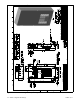
6. Remove the 4 SPD mounting screws.
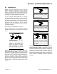
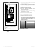
ADV-8444
1. Normal source service disconnect circuit breaker
2. Ground
3. Terminal block TB1 location
4. SPD module
5. Neutral
3
4
1
2
5
Figure 6-1 SPD Module Replacement, 200 Amp SE
Models