
RDT Transfer Switch Spec Sheet

G11-139 (Model RDT Automatic Transfer Switch) 3/20f Page 5
Accessories
- Auxiliary position-indicating contacts
D One closed on normal position and one closed on emergency
position
D Form C contacts rated 15 A @ 250 VAC
- Accessory board
D Alarm horn indicates system faults
D Adjustabletimedelays:
d Engine start
d Engine cooldown
d Preferred to standby
d Standby to preferred
d Exercise duration
D Inputs and Outputs:
d Remote start/stop input (loaded)
d Programmable exerciser input
d Generator set supplying load output:
10 A @ 120 V SPST normally open (NO) contact
D External alarm module connection
D Dip switches:
d 1 week/2 week exerciser
d Load/no load exercise mode (for optional programmable
exerciser)
d Momentary/maintained external start/stop input:
Selects momentary (1 second) push button or maintained
contact closure for remote start/stop signal
d Load control, 5 minutes/10 minutes:
Allows adjustment of the startup delay after transfer to
generator set for selected loads (e.g. air conditioners or other
large motor starting loads)
d Audible alarm disable
- External alarm module
D Alarm horn
D Alarm silence/lamp test button
D Remote start/stop button
D Generator supplying load indicator
D Fault indicator
D Fits into standard outlet box
D Multiple alarm modules can be connected
D Accessory board required
- Load shed kit
D Automatically sheds non-critical loads when essential appliances
are running
D Prevents generator overload in compliance with NEC 2008
D Provides two (2) HVAC relays, rated 10 A @ 125 VAC, to control
two independent air conditioner loads
D Includes four (4) pilot relays rated 120VAC, 125VA (pilot duty),
10 A @ 125 VAC (general purpose) to control customer-provided
power relays for non-essential loads
D Mounts inside the ATS enclosure
D Uses Kohler ’s exclusive RBUS communication protocol
D Requires Kohlerr residential generator set with RDC2 or DC2
controller
D See specification sheet G11- 124
- Power relay modules
D 50 amp power relay mounted in a NEMA Type 3R enclosure
D Useuptofourmoduleswiththeloadshedkit
D UL/cUL listed
D Dimensions: 172 x 233 x 92 mm (6.8 x 9.2 x 3.6 in.)
D For more information, see specification sheet G6-143
- Programmable exerciser
D Seven-day programmable timer allows scheduling up to 56
on/off events
D LCD display indicates day, time, program/run modes, and
on/off/skip status
D Skip next cycle button
D Lithium backup battery with 5-year expected life
D Accessory board required
- Wall-mount bezel (for Type 1 enclosures)
D For 100 and 200 amp recess-mounted switches
D For NEMA type 1 enclosures only (not for NEMA 3R or service
entrance switches)
Additional Accessories for
Service Entrance Models
- Accessory circuit breaker
D For generator set engine heater or other AC accessory
D 15 A single-pole Square D type QO circuit breaker
- Enclosure space heater
D 150 Watts
D Hygrostat (humidity control)
D Built-in temperature limiter for overheat protection
D 15 A single-pole Square D type QO circuit breaker
- Utility-side surge suppressor
D Surge protection reduces transient v oltages to harmless levels
D Protection modes: L-L / L-N / L-G / N-G
D Replaceable phase and neutral cartridges for service
D Frequency: 50- 60 Hz
D Operating Temperature Range: - 40 to 176_F
(- 40 to 80_C)
D Remote contacts for customer-supplied status indicators:
Contacts: 1 NO, 1 NC
Min Load: 12VDC / 10 mA
Max. Load: 250 VAC / 1 A
Wire Size (max.): 16AWG
D Fuse protection: 30 amps / 600 V
D UL 1449, 3rd Edition for Type 2 applications
D IEC 61-643-1, 2nd Edition T2/11
D See additional specifications below
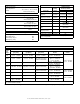
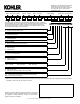
Surge Suppressor Specifications
Nominal
Voltage
(V ±15%)
Max.
Discharge
Current
(kA)
Phase Poles
UL VPR 3rd Ed
(L-N/N-G/L-G)
(kV)
Limiting Voltage, (L-N/N-G/L-G)
(kV)
Short Circuit
Withstand
Current (kA)
Maximum
Continuous
Operating
V
oltage (
V
AC)
at 3kA at 10kA
240 / 120 40 Split 3 0.6 / 1.2 / 0.7 0.6 / 0.4 / 0.6 0.8 / 0.7 / 0.8 200 175 / 350