
RDT Spec Sheet
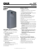

G11-139 (Model RDT Automatic Transfer Switch) 3/20f Page 2
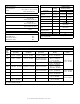
Environmental Specifications
Operating temperature:
−
20_Cto70_C(
−
4_F to 158_F)
Storage temperature:
−
40_Cto85_C(
−
40_F to 185_F)
Humidity:
5 to 95% noncondensing
Contact Ratings
Engine start 0.5 A @ 125 VAC;
2A@30VDC
SPST normally closed (NC)
Common fault 0.5 A @ 125 VAC;
2A@30VDC
SPST normally open (NO)
Load control 10 A @ 120 VAC
SPST normally open (NO)
Auxiliary contacts (optional) 15 A @ 277 VAC
Form C
Source Sensing
Undervoltage dropout 80%
Undervoltage pickup 85%
Underfrequency dropout 90%
Underfrequency pickup 96%
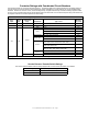
Time Delays
Time Dela
y
Factory
Setting
Adjustment with
Accessory Board*
Range Increment
Engine start 3 seconds 1- 10 seconds 1 second
Transfer from Normal to
Emergency
3 seconds 1- 10 seconds 1 second
Retransfer from
Emergency to Normal
6minutes 3- 30 minutes 3minutes
Engine cooldown 5minutes 1- 10 minutes 1minute
Exercise run time 20 minutes 5- 50 minutes 5minutes
Exercise interval 1week
1 week/2 week
(DIP switch)
Load control connection
delay
5minutes
5or10minutes
(DIP switch)
Failure to acquire
Emergency source
78 seconds NA
Undervoltage dropout 0.5 second NA
Underfrequency dropout 3 seconds NA
* Optional accessory board required for time delay adjustments
NA = not adjustable
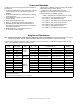
Cable Sizes
AL/CU UL-Listed Solderless Screw-Type Terminals for External Power Connections
Switch
Size,
Amps
Range of Wire Sizes, Cu/Al
Normal
(per phase)
Emergency
(per phase)
Load
(per phase)
Neutral Ground
100 (1) #14 - 1/0 AWG (1) #14 - 1/0 AWG (1) #14 - 1/0 AWG
(5)#12- 250MCM(Cu)or
(5) #10 - 250 MCM (Al)
(9) #14 - #6 AWG
(4) #14 - 1/0 AWG
100 B (1) #14 - 1/0 AWG (1) #14 - 1/0 AWG
per customer-supplied
branch circuit breakers
(26) #14 - #4AWG or
(2) #14 - 1/0 AWG or
(1) #6 - 2/0 AWG
200 (1) #6 AWG - 250 MCM (1) #6 AWG - 250 MCM (1) #6 AWG - 250 MCM
(5)#12- 250MCM(Cu)or
(5) #10 - 250 MCM (Al)
200 B (1) #6 AWG - 250 MCM (1) #6 AWG - 250 MCM
per customer-supplied
branch circuit breakers
(38) #14 - #4 AWG or
(3) #14 - 1/0 AWG or
(1) #4 AWG - 250 MCM
200 BSE (1) #4 - 300 MCM (1) #6 - 250 MCM
per customer-supplied
branch circuit breakers
(4)#12- 250MCM(Cu)or
(4) #10 - 250 MCM (Al)
(9) #14 - #6 AWG
(4) #14 - 1/0 AWG
200 SE (1) #4 - 300 MCM (1) #6 - 250 MCM (1) #6 AWG - 250 MCM
(5)#12- 250MCM(Cu)or
(5) #10 - 250 MCM (Al)
400 (2) #6 – 250 MCM (2) #6 – 250 MCM (2)#6–250MCM
(3) #4 – 600 MCM
(6) 1/0 – 250 MCM
(6) #6 – 3/0 AWG
400 SE
(1) #1 - 600 MCM or
(2) #1 – 250 MCM
(2) #6 - 250 MCM (2)#6–250MCM
(3) #4 – 600 MCM
(6) 1/0 – 250 MCM
B = Load center model
SE = Service entrance model
Note: Data is subject to change. Refer to the transfer switch dimension drawings and wiring diagrams for planning and installation.