
RDT Transfer Switch Manual


TP-6345 9/1314 Section 2 Installation
2.3 Installation
NOTICE
Foreign material contamination. Cover the transfer switch
during installation to keep dirt, grit, metal drill chips, and other
debris out of the components. Cover the solenoid mechanism
during installation. After installation, use the manual operating
handle to cycle the contactor to verify that it operates freely.
Do not use a screwdriver to force the contactor mechanism.
NOTICE
Hardware damage. The transfer switch may use both
American Standard and metric hardware. Use the correct size
tools to prevent rounding of the bolt heads and nuts.
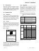
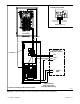
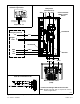
Check the system voltage and frequency. Compare
the voltage and frequency shown on the transfer switch
nameplate to the source voltage and frequency. See
Figure 2-3. Do not install the transfer switch i f the
voltage and frequency are different from the normal
(utility) source voltage and frequency or the emergency
source voltage and frequency shown on the generator
set nameplate.
1
tp6345
1. Nameplate
2. Connection instructions
3. Rating label
2
3
Figure 2-3 Enclosure Door or Inner Panel
Plan the installation. Use the dimensions given on the
enclosure dimension (ADV) drawings in Section 7.
Select a mounting site that complies with local electrical
code restrictions for the enclosure type. Mount the
transfer switch as close to the load and power sources
as possible. Allow adequate space to open the
enclosure and service the switch.
Wall mounting. Mount the transfer switch to a wall or
other rigid vertical supporting structure. Use the
template provided with 100 and 200 amp switches to
locate the mounting holes in the wall. Level the template
before marking and drilling the holes. For 400 amp
switches, refer to the dimension drawing in Section 7 for
hole locations.
Cover or remove the transfer switch’s internal
components to protect them from drill chips or debris
during installation. Use a vacuum cleaner to remove
debris from the enclosure. Tighten the mounting screws
to 2.9 Nm (26 in. lb.) when reinstalling the components.
Note: Do not use compressed air to clean the switch.
Cleaning with compressed air can cause debris
to lodge in the components and cause damage.
Clearance holes through the back of each enclosure are
provided for mounting. Use shims to plumb the
enclosure.
NEMA 3R enclosures. To remove the enclosure’s front
panel, support the panel while removing the screws.
Pull the bottom of the panel out and down until the top
clears the enclosure. Remove the inner panel to access
the transfer switch components.
100 and 200 amp NEMA 3R enclosures have locking
tabs at the bottom of the enclosure and the door. While
the enclosure is open, turn the locking tab out so that the
door can be locked with a padlock after installation is
complete.
Note: The mounting holes on NEMA 3R enclosures
have gaskets to seal out moisture. Use washers
with the mounting screws to protect the gaskets.
Recessed mounting. All 100 amp NEMA 1 enclosures
and 200 amp NEMA 1 enclosures without the load
center can be recess-mounted between 16 in. O.C. wall
studs.
Remove the ATS components from inside the enclosure
to protect them from drill chips and debris. Drill four
mounting holes in one side of the enclosure. Mark and
drill matching mounting holes in the wall stud. The
enclosures are 330.2 mm (13 in.) wide. Add a stud to
provide support on both sides of the transfer switch, if
desired.
Mount the transfer switch enclosure. Use a vacuum
cleaner to remove debris from the enclosure. Reinstall
the internal components and tighten the mounting
screws to 2.9 Nm (26 in. lb.).
Bezel. The optional bezel can be used with
recess-mounted units. After mounting the transfer
switch, mount the bezel around the transfer switch using
the six self-tapping screws included with the kit. Drywall
anchors may be needed for screws that do not go into
studs.