
RDT Transfer Switch Manual


TP-6345 9/1316 Section 2 Installation
2.5 Electrical Wiring
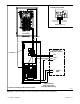
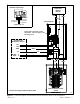
The connection drawings in Figure 2-8 and Figure 2-9
show examples of essential load and whole-house
configurations. Figure 2-10 and Figure 2-11 show
service entrance model connections.
All wiring must comply with applicable national, state,
and local electrical codes. Use separate conduit for AC
power wiring and low-voltage DC, control, and
communication system wiring.
Hazardous voltage.
Will cause severe injury or death.
Disconnect all power sources before
opening the enclosure.
DANGER
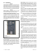
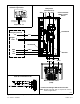
Refer to the connection diagrams on the transfer switch
enclosure door (see Figure 2-3) and the wiring
diagrams in Section 7 during installation.
Making line or auxiliary connections. Hazardous voltage
can cause severe injury or death. To prevent electrical
shock deenergize the normal power source before making any
line or auxiliary connections.
Grounding electrical equipment. Hazardous voltage can
cause severe injury or death. Electrocution is possible
whenever electricity is present. Ensure you comply with all
applicable codes and standards. Electrically ground the
generator set and related equipment and electrical circuits.
Turn off the main circuit breakers of all power sources before
servicing the equipment. Never contact electrical leads or
appliances when standing in water or on wet ground because
these conditions increase the risk of electrocution.
2.5.1 Load Center Circuit Breakers
The ATS load center uses Square D type QO breakers.
Up to 8 type QOT tandem breakers can also be used. In
an essential load application, the breakers can be
moved from the main panel to the load center if the main
distribution panel uses the same type of breakers.
Otherwise, obtain and install new Square D type QO
circuit breakers. The rating of the load center circuit
breaker must match the rating of the existing breaker in
the main panel for each circuit. If circuit breakers are
removed from the load panel, install cover plates over
the vacant positions. Cover plates can be obtained from
a local Square D supplier.
Verify that the total rating for all breakers used in the load
center does not exceed the rating of the transfer switch.
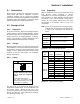
2.5.2 AC Power Connections
Determine the cable size. Refer to Figure 2-7 to
determine the cable size required for the transfer switch.
Make sure the lugs provided are suitable for use with the
cables being installed.
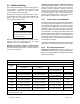
Cable Sizes
AL/CU UL-Listed Solderless Screw-Type Terminals for External Power Connections
Switch Size,
Amps
Range of Wire Sizes, Cu/Al
Normal and Emergency
(per phase)
Load
(per phase)
Neutral Ground
100 (1) #14 to 1/0 AWG (1) #14 to 1/0 AWG
(3) #12 to 250 KCMIL (Cu) or
(3) #10 to 250 KCMIL (Al)
(9) #14 to #4 AWG
100 B (1) #14 to 1/0 AWG (1) #14 to 1/0 AWG (1)#6to2/0AWG (9) #14 to #4 AWG
200
(1) #6 AWG to 250 KCMIL (1) #6 AWG to 250 KCMIL
(3) #12 to 250 KCMIL (Cu) or
(3) #10 to 250 KCMIL (Al)
(9) #14 to #4 AWG
200 B (1) #6 AWG to 250 KCMIL (1) #6 AWG to 250 KCMIL (1) #4 AWG to 250 KCMIL (9) #14 to #4 AWG
200 BSE (1) #4 AWG to 250 KCMIL (1) #4 AWG to 250 KCMIL
(3) #12 to 250 KCMIL (Cu) or
(3) #10 to 250 KCMIL (Al)
(4) #14 to #1/0
AWG
200 SE (1) #4 AWG to 300 KCMIL (1) #6 AWG to 250 KCMIL
(3) #12 to 250 KCMIL (Cu) or
(3) #10 to 250 KCMIL (Al)
(3) #14 to #1/0
AWG
400
(2) #1/0 AWG to 250 KCMIL or
(1) #4 AWG to 600 KCMIL
(2) #1/0 AWG to 250 KCMIL or
(1) #4 AWG to 600 KCMIL
(6) #1/0 AWG to 250 KCMIL or
(3) #4 AWG to 600 KCMIL
(3)#6to3/0AWG
400 SE (2) #1/0 AWG to 250 KCMIL
(2) #1/0 AWG to 250 KCMIL or
(1) #4 AWG to 600 KCMIL
(6) #1/0 AWG to 250 KCMIL or
(3) #4 AWG to 600 KCMIL
(3)#6to3/0AWG
B = Load center model
SE = Service entrance model
Figure 2-7 Cable Sizes