
RDT Transfer Switch Manual


TP-6345 9/13 21Section 2 Installation
tp6345
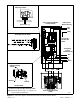
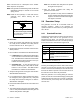
Main Distribution Panel
(Load)
Utility Power
(Normal Source)
NL1
NL2
GRD *
N*
EL1
EL2
Service Entrance Model
Transfer Switch
LL2
LL1
N*
GRD *
Emergency
Source
(Generator set)
Terminal Block TB1 detail
GRD *
Engine Start, 3, 4
Load Control,
1, 2 (optional)
Engine Start Connection to ATS
Main Logic Board
Common Fault,
5, 6 (optional)
L0
* Connect according to NEC and local codes.
Note: Neutral-to-ground strap is required for
service entrance applications.
Neutral Bonding
Jumper
Ground
Neutral
Ground Detail
To Ground. *
See Ground
Detail
Figure 2-11 Connection Diagram, 400 Amp Service Entrance Model Transfer Switch