
RDT Transfer Switch Manual


TP-6345 9/13 25Section 2 Installation
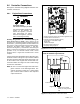
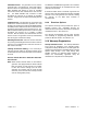
2.7.4 SE Model Bat tery Charger Circuit
Breaker Connection
The SE model transfer s witch has a 15-amp single-pole
circuit breaker for the generator set battery charger. The
circuit breaker (CB1) is factory-wired to the accessory
connection terminal block TB1. Connect the battery
charger power connection to the accessory connection
terminal block. For connections, see Figure 2-19 or the
wiring diagrams in Section 7, Diagrams and Drawings.
See Figure 2-20 for the terminal block location.
GM49826B
SPD
Figure 2-19 Accessory Connection Terminal Block,
SE Model Only
4
ADV-8444
1. Accessory circuit breakers
2. Hygrostat for optional heater
3. Enclosure heater
4. Accessory connection terminal block
5. Accessory board
1
Enclosure Interior, Side View
2
3
5
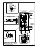
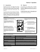
Figure 2-20 SE Model Accessory Locations, Typical
2.7.5 SE Model Accessory Connections
See Figure 2-20 or the dimension drawings in Section 7
for the locations of optional accessories.
The following connections can be made to accessory
connection terminal block TB1. See Figure 2-20 for the
terminal block location.
Engine Heater. Engine heater circuit breaker CB2 is a
15-amp single-pole circuit breaker. CB2 is optional on
200 Amp SE models and standard on 400 Amp SE
models.
If the generator set is equipped with a carburetor heater,
connect the heater power to engine heater circuit
breaker CB2 through terminal block TB1. See
Figure 2-20 for the terminal block location. For
connections, see Figure 2-19 or the transfer switch
wiring diagram in Section 7, Diagrams and Drawings.
SPD Remote Indicator. An indicator for the optional
surge protective device (SPD) can also be connected to
the accessory connection terminal block. The SPD
provides for remote monitoring via a normally open (NO)
or normally closed (NC) circuit. The contact changes
state when the SPD module needs replacement.
Connect customer-provided indicators or alarms to the
SPD auxiliary contact terminals (Normal and
Emergency) on terminal block TB1 to provide remote
indication when the SPD needs to be replaced. See
Figure 2-21 for the contact rating. See Figure 2-19 or
the service entrance transfer switch wiring diagram in
Section 7, Diagrams and Drawings, for connections.
Description Contact Rating
SPD Remote Indication Contact 2 A @ 250 VAC
Figure 2-21 Contact Rating
Enclosure Space Heater. The enclosure space heater,
if installed, is factory-wired to circuit breaker CB3
through terminal block TB1. Check the temperature and
humidity settings on the space heater control. See
Section 4.4.3 for recommended settings.
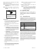
2.8 Operation Test
Use the procedure below to run the transfer switch’s test
sequence. Loaded or unloaded test sequences can be
run. The test sequence starts the generator set, and, for
a loaded test, transfers the load to the emergency
source. When the test ends, the transfer switch
transfers the load back to the normal source and
removes the engine start signal.