
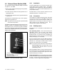
RDT Transfer Switch Manual


TP-6345 9/13 33Section 4 Accessories
Section 4 Accessories
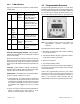
4.1 Accessory B oard
The optional accessory board is mounted above the
controller’s main logic board. The accessory board kit is
available factory-installed or as a loose kit. See
Figure 2-17 and Figure 4-1 for the accessory board
location.
The accessory board contains the following
components:
D Audible alarm on system faults.
D Rotary switches for time delay adjustments.
D DIP switches for exercise, remote test switch
operation, and load control functions.
D Connector for remote test input, programmable
exerciser input, and generator set supplying load
output.
D Connector for the optional External Alarm Module
(EAM)
The accessory board is required if the External Alarm
Module (EAM) is installed. See Section 4.2.
Note: Before opening the transfer switch enclosure to
access the accessory board, open the circuit
breakers to disconnect the power to the transfer
switch.
4.1.1 Audible Alarm
The audible alarm sounds on the fault conditions shown
in Section 3.3.
Always identify and correct the cause of the fault
condition before resetting the controller. Press and hold
the test and exercise pushbuttons on the controller to
clear the fault and silence the alarm.
4.1.2 EAM Connection (P13)
Connect the optional External Alarm Module (EAM) to
P13. See Figure 4-2 for the location of connector P13.
See Section 4.2.2 for EAM connection instructions.
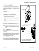
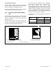
GM38796
Note: Long pins of connector
go into accessory board.
Detail
A
See Detail A
Accessory Board
Insert connector in P8 on back of board.
Line up snap studs and connector on board
with main logic board and press together.
CONNECTOR
Main Logic
Board
Accessory
Board
Figure 4-1 Accessory Board Installation