
RDT Transfer Switch Manual


TP-6345 9/13 29Section 3 Operation
Section 3 Operation
3.1 Introduction
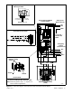
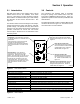
Red and green LEDs on the transfer switch controls
indicate which sources are available, show which
source is connected to the load, and flash to indicate
fault conditions. Pushbuttons allow you to start and stop
the generator set and set the exercise timer. See
Figure 3-1.
The transfer switch uses fixed settings for time delays,
voltage and frequency pickup and dropout, and other
system settings. An optional accessory board allows
changes to the time delays and exerciser settings and
provides connections for remote test and remote
exercise inputs. See Section 4.1 for information on the
accessory board.
3.2 Controls
The controller’s user interface panel is accessible
through an opening in the transfer switch cover (the
inner panel on NEMA type 3R enclosures). Figure 3-1
explains the operation of the controller pushbuttons and
LED indicators.
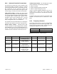
The LEDs light steadily or flash to indicate different ATS
conditions as shown in Figure 3-2. See Section 3.3 for
more information on fault conditions.
Generator Source Available LED. Red LED
lights when the the ATS detects acceptable
voltage from the generator set. Flashes to
indicate faults; see Figure 3-2.
Exercise Button. Press and hold 3
seconds to set the exerciser to run the
generator set. Generator source LED
flashes. Press and hold for 6 seconds to set
the exerciser to start the generator set and
transfer the load. Generator source and
position LEDs flash. The exerciser will run
at the same day and time each week. Press
again and hold for 2 seconds to end the
exercise.
GM82156
Test Button. Press and hold for 3 seconds
to start the generator set. Generator source
LED flashes.
Press and hold for 6 seconds to start the
generator set and transfer the load.
Generator source and position LEDs flash.
Press again and hold for 2 seconds to end
the test.
Utility Source Position LED.
Green LED lights when the electrical
load is connected to the Normal sourc
e
(typically utility power). Flashes to
indicate faults; see Figure 3-2.
Utility Source Available LED. Green LED
lights when the the ATS detects acceptable
voltage from the utility power source. Also see
Figure 3-2.
Generator Position LED.
Red LED lights when the electrical
load is connected to the generator
set. Flashes to indicate faults; see
Figure 3-2
.
Figure 3-1 User Interface Panel
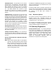
Condition LED Indication
Utility source power available Utility Source Available LED lights steadily.
Load connected to utility power Utility Source Position LED lights steadily.
Generator set power available GEN Source Available LED lights steadily.
Load connected to the generator set GEN Position LED lights steadily.
Loaded test GEN Available and GEN Position LEDs flash on 1 second, off 1 second.
Unloaded test GEN Available LED flashes on 1 second, off 1 second.
Loaded exercise GEN Available and GEN Position LEDs flash on 0.5 second, off 2 seconds.
Unloaded exercise GEN Available LED flashes on 0.5 second, off 2 seconds.
Failure to acquire standby source fault GEN Available LED flashes 2 times/second.
Failure to transfer fault GEN or Utility Source Position LED flashes 2 times/second.
Auxiliary switch failure fault GEN Position and Utility Source Position LEDs flash alternately 2 times/second.
Figure 3-2 LED Indication