
RDT Transfer Switch Manual

TP-6345 9/1322 Section 2 Installation
2.6 Controller Connections
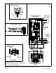
See Figure 2-12 and the wiring diagrams in Section 7 for
controller connections.
2.6.1 Engine Start Connections
Accidental starting.
Can cause severe injury or death.
Disconnect the battery cables before
working on the generator set.
Remove the negative (--) lead first
when disconnecting the battery.
Reconnect the negative (--) lead last
when reconnecting the battery.
WARNING
Disabling the generator set. Accidental starting can
cause severe injury or death. Before working on the
generator set or connected equipment, disable the generator
set as follows: (1) Move the generator set master switch to the
OFF position. (2) Disconnect the power to the battery charger.
(3) Remove the battery cables, negative (--) lead first.
Reconnect the negative (--) lead last when reconnecting the
battery. Follow these precautions to prevent starting of the
generator set by an automatic transfer switch, remote
start/stop switch, or engine start command from a remote
computer.
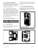
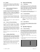
Connect the engine start leads from the generator set to
terminals 3 and 4 on the green 6-pin connector labeled
P2 on the controller’s main logic board. See Figure 2-12
for the location of the engine start contacts and V for
connection details. See Figure 2-15 for contact ratings
and wire size information.
Note: Be sure to connect the engine start leads to the
green connector on the main logic board.The
optional accessory board has a similar black
6-pin connector that is used for other input and
output connections.
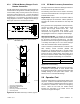
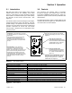
GM35950
1. RS-232 connection (used to load controller application code)
2. Contactor harness connection P1
3. Customer connection terminal P2 (green):
Load control or normal failure output
Engine start
Common fault output
4. Accessory board connector P3
5. Frequency shunt (jumper) P5
2
3
BARCODE
6
7
12
1
P1
R69
R33
C31
C39
+
K2
K1
C11
+
VR2
R34
K5
VR1
D7
R36
Z1
+
C12
C15
R31
Q3
C26
D18
R68
D6
R32
K3
L1
K4
Z2
R37
C19
+
Z5
C27
+
C32
D9
D19
C30
D1
R19
+
R70
C13
R47
U1
R59
D2
Q2
C50
C5
R11
2212
11
1
44 34
33
23
U2
50
60
P5
FREQUENCY
+3.3V
GND
+12V
R23
C40
U3
R72
C38
D17
C22
C8
C37
C21
R3
R61
C44
R52
R9
R77
C36
U5
R5
C20
C46
R10
R39
R29
R56
R16
C47
R58
C14
+
C6
R46
D15
R40
C54
R63
C35
C24
R57
R65
R60
R76
R54
C41
R41
R27
R15
R55
C43
R13
R43
Q1
R25
R50
D16
C7
R4
C51
R14
R51
R35
C42
R6
R44
R74
R75
D12
R30
C10
+
C3
D14
C53
D13
C2
C49
R53
R42
C25
R18
R7
C28
R38
R12
R71
R67
C23
R62 R64
C52
C9
C48
R73
R26
R28
P7
R45
R17
C45
C4
R8
P2
R66
6
4
3
P4
1
P6
D8
2
D11
43
1
D10
P3
C29C34
D5
D3
D4
C55
U4
R24
R22
R21
V4
34
V1
5
18
1
V2
L2
V3
3
1
6
2
Z3
C18
C1
R48
R20
Y1
R49
C17
R1
C16
Z4
C33
R2
4
1
5
Figure 2-12 Controller Board Connections
Load Control or Normal
Failure (see wiring decal on
unit)
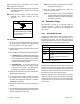
Connection Detail, Engine Start
Leads to ATS Main Logic Board P2
Common Fault
6CFCOM
5CFNO
2LCORNFCOM
1LCNOorNFNC
3ENGINESTART
4ENGINESTART
Engine Start
Figure 2-13 Engine Start Connection Detail