
RDT Transfer Switch Manual


TP-6345 9/13 31Section 3 Operation
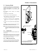
3.5.2 Transfer Sequence
Figure 3-4 illustrates the transfer sequence when the
normal source fails and Figure 3-5 illustrates the
sequence when it returns. Time delays before load
transfer prevent nuisance transfers during brief power
interruptions. See Figure 3-6. Events such as the
failure of the generator set to start can change the
sequence of operation.
The Failure to Acquire Emergency Time Delay is set for
78 seconds to allow for three 15-second engine
cranking cycles plus 15 seconds rest between starting
attempts.
If the emergency source fails and the normal source is
not available, the transfer switch controller powers down
until one of the sources returns.
The optional accessory board allows time delay
adjustments. See Section 4.1.
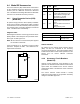
Transfer time delay from normal to emergency
source, 3 sec. *
Load control time delay *
* Optional accessory board allows adjustment of these time
delays.
[ Delays startup of selected loads by 5 or 10 minutes,
adjustable by DIP switch on optional accessory board.
Engine start time delay, 3 sec. *
Normal power source voltage falls below 80% of
nominal
Undervoltage dropout time delay, 0.5 seconds
(fixed)
Transfer to emergency source
Load control contact opens
Engine start contacts close
Load control contact closes
Figure 3-4 ATS Sequence of Operation, Transfer to
Emergency
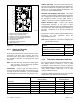
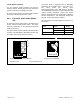
Retransfer from Emergency to Normal *
Transfer to the utility source
Time delay engine cooldown *
Engine start signal removed
Normal power source voltage rises
above 85% of nominal
* Optional accessory board allows adjustment of these time
delays. See Figure 3-6.
Figure 3-5 ATS Sequence of Operation, Retransfer
to Normal
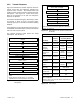
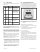
Time Delays
Time Delay
Factory
Setting
Adjustment with
Accessory Board*
Range Increment
Engine Start 3 seconds
1--10
seconds
1 second
Transfer from
Normal to
Emergency
3 seconds
1--10
seconds
1 second
Retransfer from
Emergency to
Normal
6 minutes
3--30
minutes
3 minutes
Engine Cooldown 5 minutes
1--10
minutes
1 minute
Failure to Acquire
Emergency
78 seconds[
NA
Exercise Time
Duration
20 minutes
5--50
minutes
5 minutes
Load Control
Time Delay
5 minutes
5 or 10 minutes
(DIP switch)
Undervoltage
Dropout Time
0.5 second NA
Underfrequency
Dropout Time
3 seconds NA
* Optional accessory board required for time delay adjustments.
NA = not adjustable
[ Allows for three 15-second crank attempts separated by two
15-second rest periods.
Figure 3-6 Time Delays