
RDT Transfer Switch Manual


TP-6345 9/13 35Section 4 Accessories
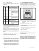
4.1.5 DIP Switches
DIP switches on the optional accessory board control
the exercise, remote test, and load control functions.
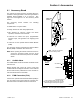
The DIP switch location is shown in Figure 4-2. The DIP
switch functions are summarized in Figure 4-5. Check
the DIP switch settings and adjust if necessary for the
application.
1 Week/2 Week Exercise. Switch 1. This switch
controls the frequency for exercise runs that are set by
pressing the Exercise button on the ATS controller. This
switch does not affect exercise periods set through the
optional programmable exerciser. If the setting is
changed after the exerciser has been set, the new DIP
switch setting becomes effective after the next exercise.
Loaded/Unloaded Exercise. Switch 2. This switch
controls automatic exercise runs. The first exercise
started by pressing the Exercise button on the controller
is not affected by this switch. All subsequent automatic
exercise runs will be loaded or unloaded according to
this switch setting.
An unloaded exercise starts and runs the generator set.
A loaded exercise starts the generator set and transfers
the electrical load. See Section 2.9, Exerciser Setup, for
more information.
Maintained/Momentary Test. Switch 3.
D With DIP switch 3 in the ON (maintained) position,
close a remote test switch or contact to start and run
the generator set. Open the remote contact to end the
test and signal the generator set to stop.
Set DIP switch 3 to ON if the EAM is connected.
D With DIP switch 3 in the OFF (momentary) position,
hold the test switch for 1 second and release to start a
test. The remote switch must be held closed for at
least 1 second. Press the test switch again to stop the
test and signal the generator set to stop.
Note: Some generator sets may continue to run for
an engine cooldown time period after receiving
the remote stop signal.
Load Control. Switch 4. Sets the load control time
delay to 5 or 10 minutes. See Section 2.6.2.
Alarm Enable. Switch 5. Enables or disables the alarm
horn on the accessory board. If this switch is changed
while the horn is sounding, allow several seconds for the
change to register and the horn to stop.
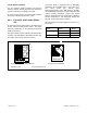
Install the front panel(s) or close and lock the enclosure
door before energizing the transfer switch.
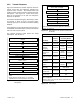
Switch Off (Open) On (Closed) Notes
1 2 Week Exercise 1 week 2 Weeks For the exercise button on the controller’s user interface.
2 Loaded Exercise Unloaded Loaded
For automatic exercise runs set at the controller (excluding the
first exercise) or set on the optional programmable exercise
timer.
3 Maintained Test Momentary Maintained
For an optional remote switch, such as the start/stop switch on
the EAM.
4 Load Control 5 Minutes 10 Minutes
For delayed connection of selected large loads to the generator
set.
5 Alarm
Alarm
Disabled
Alarm
Enabled
For the alarm horn on the accessory board (inside the ATS
enclosure). Does not affect the alarm horn on the External
Alarm Module.
Figure 4-5 Accessory Board DIP Switches