
RDT Transfer Switch Manual


TP-6345 9/13 11Section 1 Description
Section 1 Description
1.1 Transfer Switch Description
An automatic transfer switch (ATS) transfers electrical
loads from a normal source of electrical power to an
emergency source when the normal source voltage or
frequency falls below an acceptable level. The normal
source is typically utility power. The emergency source
is usually a generator set.
When the normal source fails, the ATS signals the
emergency source generator set to start. When the
emergency source reaches acceptable levels and
stabilizes, the ATS transfers the electrical load to the
emergency source.
The ATS continuously monitors the normal source and
transfers the load back when the normal source returns
and stabilizes. After transferring the load back to the
normal source, the ATS removes the generator start
signal, allowing the generator set to shut down.
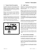
Figure 1-1 shows a typical installation block diagram.
Power
Switching
Device
To Load
Automatic Transfer Switch
Electrical
Controls
Normal
(Utility)
Power
Emergency
(Generator)
Power
Generator
Start Generator
TS-003
Figure 1-1 Typical ATS Block Diagram
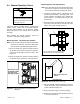
1.2 Load Centers
Model RDT 100 and 200 amp transfer switches are
available with or without built-in l oad centers. Models
without load centers require the installation of a
separate load panel.
Loads. The transfer switch can be connected to supply
all of the electrical loads in the home, or only the
essential loads such as the furnace, refrigerator, well
pump, and selected light circuits. Identify the essential
circuits that must be supplied during a power outage.
Verify that the generator set and transfer switch are
adequately rated to supply all of the selected loads.
Circuit breakers. Because the size and number of
circuit breakers required will vary with each application,
circuit breakers are not provided with the transfer switch
load center.
Determine the circuits that will be connected to the
transfer switch (essential loads). Identify the breakers
for those circuits in the main distribution panel.
The ATS load center requires Square D type QO
breakers. Up to 8 type QOT tandem breakers can be
used on 100 amp models. If the main distribution panel
uses the same type of breakers, the breakers can be
moved from the main panel to the load center.
Otherwise, obtain new Square D type QO circuit
breakers. For each circuit, the rating of the load center
circuit breaker must match the rating of the existing
breaker in the main panel.
Verify that the total rating for all of the breakers used in
the load center does not exceed the rating of the transfer
switch.
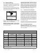
1.3 Service Entrance Models
Service entrance models use a circuit breaker to provide
the service disconnect for the utility source.
The SE model is equipped with a 15-amp, single-pole
circuit breaker for the generator set battery charger.
A circuit breaker for the generator set engine heater is
available as an optional accessoryfor the 200 amp SE
model. The engine heater circuit is standard on the 400
amp SE model.
A surge suppressor for the utility source and an
enclosure space heater are also available as optional
accessories.