
RDT Transfer Switch Manual


TP-6345 9/13 19Section 2 Installation
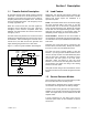
tp6345
Main Distribution Panel
(Load)
Service
Disconnect
(Normal
Source)
L0
GRD
Engine
Start
* Connect according to NEC and local codes.
Generator Set
(Emergency Source)
NL1
NL2
GRD *
N*
3
4
GRD *
Transfer Switch
GRD *
N*
LL2LL1
N*
EL1
EL2
Engine start connections 3 and 4.
See Detail A. Also see Figure 2-13
and wiring decal.
Ground
Engine Start, 3, 4
Load Control or
Normal Failure,
1, 2 (optional)
Detail A, Engine Start Leads to
ATS Main Logic Board
Common Fault,
5, 6 (optional)
Figure 2-9 Connection Diagram, Transfer Switch without Load Center, Whole-House Configuration