
RDT Transfer Switch Manual


TP-6345 9/13 23Section 2 Installation
2.6.2 Optional Controller Connections
The green 6-pin connector P2 on the controller’s main
logic board provides connection points for optional
common fault and load control or normal failure circuits.
See Figure 2-12 for the connector location and
Figure 2-13 for connection details. See Figure 2-15 for
contact ratings, connection, and wire size information.
Load Control Contact. Normally open (NO) contact
provided on most models; see the wiring decal on the
unit. Provides a delayed contact closure to allow startup
of selected loads 5 minutes after transfer to the
emergency power source (generator set). Use this
contact to delay startup of equipment with large
motor-starting loads such as air conditioners.
The optional accessory board allows you to change the
load control time delay to 10 minutes. See Section 4.1.
Normal Failure Contact. Normally-closed (NC)
contact provided on models equipped with controller
board GM41597 only; see the wiring diagram decal on
the unit. This contact opens when the normal source is
available and closes when the normal source is lost.
Common Fault Contact. The normally open contact
closes and latches on the following conditions:
D Failure to transfer
D Position-indicating auxiliary contact fault
D Failure to acquire emergency source
Connect customer-supplied equipment such as an
indicator lamp or alarm horn to the common fault
connections on connector P2. See Section 3.3 for fault
information.
The faults must be reset to open this contact after a fault
condition. See Section 3.4 for instructions to reset
faults.
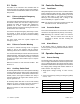
2.6.3 Frequency Selection
The transfer switch frequency is set by a programming
shunt (jumper) on P5 on the main logic board. See
Figure 2-12 for the jumper location. Position the jumper
as indicated in Figure 2-14 for 50 or 60 Hz.
Frequency P5 Jumper Position
50 Hz P5-1 to P5-2
60 Hz P5-2 to P5-3
Figure 2-14 Frequency Jumper Positions
Description Terminals Contact Rating Wire Size Tightening Torque Max. Distance
Load Control P2-1 and P2-2
10 A @ 120 VAC
Normally open (NO)
#12--24 AWG 0.8Nm(7in.lb.) 213 m (700 ft.)
Normal Failure
(control board
GM41597 only)
P2-1 and P2-2
10 A @ 120 VAC
Normally closed (NC)
#12--24 AWG 0.8Nm(7in.lb.) 213 m (700 ft.)
Engine Start P2-3 and P2-4
0.5 A @ 125 VAC;
2A@30VDC
Normally closed (NC)
#12--24 AWG 0.8Nm(7in.lb.) 213 m (700 ft.)
Common Fault P2-5 and P2-6
0.5 A @ 125 VAC;
2A@30VDC
Normally open (NO),
latches closed
#12--24 AWG 0.8Nm(7in.lb.) 213 m (700 ft.)
Figure 2-15 Controller Main Logic Board Customer Connections (P2)