
RDT Transfer Switch Manual


TP-6345 9/1324 Section 2 Installation
2.7 Accessory C onnections
Factory-installed accessories may require power, input,
and output connections. Refer to the following sections
and Section 4 for instructions to connect optional
accessories. Check settings on optional accessories as
described in the following sections.
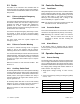
2.7.1 Auxiliary Contacts (Optional)
Optional auxiliary contacts provide one set of contacts
that close when the transfer switch is in the Normal
position and one set of contacts that close when the
transfer switch is in the Emergency position. Use 1/4 in.
fast-on connectors to connect the auxiliary contacts to
customer-supplied alarms, remote indicators, or other
devices. See Figure 2-16 for the contact rating.
The auxiliary contacts are located on the right side of the
contactor. See Figure 2-18.
The 400 amp models are equipped with one set of
auxiliary contacts as standard equipment.
Description Contact Rating
Auxiliary Contacts 15 A @ 277 VAC Form C
Figure 2-16 Auxiliary Contact Rating
2.7.2 Accessory Board
If the accessory board is installed, check the DIP
switches and time delay settings and set them to the
desired values. See Section 4.1.
A remote start/stop (remote test) switch and an external
exerciser can be connected to the accessory board.
See Section 4.1.3 for input and output connection
instructions.
2.7.3 External Alarm Module (EAM)
Use category 5 network cable to connect the optional
EAM (if used) to the accessory board. See Section 4.2.
The accessory board is required for connection and
operation of the EAM.
1
GM82988
1. Accessory board (optional)
2. Programmable exerciser (optional)
2
Figure 2-17 Optional Accessory Locations, Typical
1. Auxiliary contacts 2. Normal 3. Emergency
GM29856
NO
NO
2
3
1
NC*
NC*
COM
COM
* NC contact provided on some switches
Figure 2-18 Optional Auxiliary Contacts, Typical