
RDT Transfer Switch Manual


TP-6345 9/1330 Section 3 Operation
3.3 Faults
The LEDs on the controller’s user interface flash as
shown in Figure 3-2 to indicate various fault conditions.
Contact an authorized distributor/dealer for service if the
fault persists.
3.3.1 Failure to Acquire Emergency
Source Warning
The Failure to Acquire Emergency Source fault occurs if
the transfer switch does not sense voltage from the
generator set within 78 seconds after signaling the
generator set to start. Check the generator set
operation and the connections from the generator set to
the ATS in the case of this fault.
The Failure to Acquire Emergency Time Delay is set for
78 seconds to allow for three 15-second engine
cranking cycles plus 15 seconds rest between starting
attempts.
The fault clears when the system acquires the
emergency source.
3.3.2 Failure to Transf er Warning
The Failure to Transfer warning occurs if a signal to
transfer is sent to the contactor and the position-
indicating contacts do not indicate a complete transfer.
The controller will attempt to transfer three times before
indicating the fault. If the transfer switch is in the Normal
position, the Engine Cooldown time delay is executed
and then the engine start contacts open to stop the
generator set.
Reset the controller to clear the fault condition. See
Section 3.4.
3.3.3 Auxiliary Switch Fault
An Auxiliary Switch fault occurs if the position-indicating
contacts indicate that the ATS position changed when
no transfer was called for. If the transfer switch is in the
Normal position, the Engine Cooldown time delay is
executed and then the engine start contacts open to
stop the generator set.
An Auxiliary Switch fault also occurs if both auxiliary
switches are open or closed so that the controller is
unable to determine the transfer switch position.
Reset the controller to clear the fault condition. See
Section 3.4.
3.4 Controller Resetting
3.4.1 Fault Reset
Always identify and correct the cause of a fault condition
before resetting the ATS controller. Press and hold the
Exercise and Test buttons for approximately 3 seconds
until the LEDs flash to clear faults and warnings.
Warnings reset automatically with a change in the
source availability or a signal to transfer.
Note: The Common Fault output remains closed until
the faults are reset. See Section 2.6.2.
3.4.2 Controller Reset
Press and hold both buttons for 6 seconds to reset the
controller to its original state at powerup, if necessary.
Note: Resetting the controller clears the exerciser
setting. Set the exercise time and day as
described in Section 2.9 after resetting the
controller.
3.4.3 Alarm Silence
If the transfer switch is equipped with an optional
accessory board, pressing both buttons will also silence
the alarm horn.
3.5 Operation Sequence
3.5.1 Source Sensing
The transfer switch controller monitors the utility power
source voltage, and initiates the transfer sequence if the
source voltage falls below the voltage dropout setting.
Retransfer is initiated when the utility source rises above
the voltage pickup settings and remains stable for at
least 6 minutes. See Figure 3-3.
D Single-phase voltage sensing on both sources,
±5%.
D Line-to-line frequency sensing on emergency (GEN)
source, ±2%.
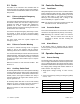
Source Sensing
Undervoltage dropout 80%
Undervoltage pickup 85%
Underfrequency dropout * 90%
Underfrequency pickup * 96%
* Emergency (GEN) source only
Figure 3-3 Source Sensing