
RDT Transfer Switch Manual


TP-6345 9/13 41Section 5 Service Disconnect, SE Model
Section 5 Service Disconnect, SE Model
Note: This section applies only to service entrance
model transfer switches.
Hazardous voltage.
Will cause severe injury or death.
This equipment must be installed and
serviced by qualified electrical
personnel.
DANGER
5.1 Service Disconnect Procedure
Use the following procedure to disconnect the utility
source on service entrance model transfer switches.
Note: Power is still present on the input side of the utility
source circuit breaker after this procedure.
1. Prevent the emergency generator set from
starting:
a. Turn the generator set OFF.
b. Disconnect power to the generator set battery
charger.
c. Disconnect the generator set engine starting
battery, negative (--) lead first.
2. On the transfer switch, remove the enclosure front
panel. Do not remove the inner panel.
3. Move the utility source circuit breaker to the OFF
position.
4. Check the LEDs on the transfer switch controller’s
user interface. Both the Utility Available and GEN
Available LEDs should be off.
Note: Power is still present on the input side of the
utility source circuit breaker. Do not remove
the protective barrier around the utility
source connection lugs.
5. To lock out the transfer switch, replace the
enclosure front panel and attach a padlock to the
hasp.
5.2 Source Circuit Breaker Reset
If the utility source circuit breaker trips due to an
overcurrent condition, the transfer switch will issue an
engine start signal and then transfer to the emergency
source when it is available.
When the circuit breaker trips, the handle moves to an
intermediate position. To reset a tripped circuit breaker.
move the handle to the extreme OFF position and then
to the ON position.
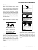
1
ADV8444-
1. Normal/utility circuit breaker
2. Padlock hasp
3. Controller’s user interface
4. Optional programmable exerciser
3
2
4
Figure 5-1 Service Entrance Model, Front Panel
Removed (200 Amp model shown)