
RXT Transfer Switch Manual

TP-6807 1/16 11Section 1 Description
Section 1 Description
1.1 Transfer Switch Description
An automatic transfer switch (ATS) transfers electrical
loads from a normal source of electrical power to an
emergency source when the normal source voltage or
frequency falls below an acceptable level. The normal
source is typically utility power. The emergency source
is usually a generator set.
Model RXT transfer switches must be connected to a
generator set equipped with the Kohlerr RDC2 or DC2
generator/transfer switch controller.
Voltage sensing data from the ATS is continuously
transmitted to the RDC2/DC2 controller mounted on the
generator set. When the normal source fails, the
RDC2/DC2 controller signals the emergency source
generator set to start. When the emergency source
reaches acceptable levels and stabilizes, the ATS
transfers the electrical load to the emergency source.
The RDC2/DC2 controller signals the ATS to transfer
the load back when the normal source returns and
stabilizes. See Section 3 for detailed operation
dscriptions.
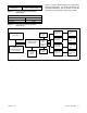
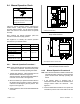
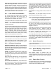
Figure 1-1 shows a typical installation block diagram.
Power
Switching
Device
To Load
Automatic Transfer Switch
Interface
Board
Normal
(Utility)
Power
Emergency
(Generator)
Power
Generator
TP-6751
Electrical
Controls
Figure 1-1 Typical ATS Block Diagram
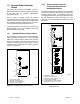
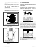
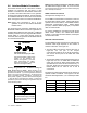
Service Entrance Model (UL)
Load Center Model Standard Model
Figure 1-2 Selected Transfer Switches
(covers removed)
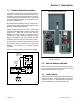
1.2 Service Entrance Models
Service entrance models use a circuit breaker to provide
the service disconnect for the utility source. A service
entrance model is shown in Figure 1-2.
1.3 Load Centers
Model RXT 100 amp transfer switches are available with
a built-in load center. A model with a built-in load center
is shown in Figure 1 -2. Models without load centers
require the installation of a separate load panel.