
RXT Transfer Switch Manual

TP-6807 1/1614 Section 1 Description
1.5 Optional Status Indicator
Panels
Two status indicator panels are available. One is for
RXTs with the standard interface board, and the other is
for the RXT with the combined interface/load
management board.
The two types of indicator panels use different
connectors and are not interchangeable. The standard
indicator panel connects only to the standard board.
The combined indicator panel connects only to the
combined interface/load management board.
If the status indicator is purchased as a loose kit (not
factory-installed), refer to the installation instructions
provided with the kit, TT- 1585.
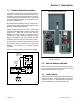
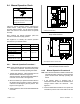
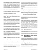
1.5.1 Standard Status Indicator Panel
A user interface panel that contains status-indicating
LEDs is available. See Figure 1-6. Source available
LEDs light to indicate that the utility and/or generator
sources are available. The utility or generator source
supplying load LED lights to show which source is
connected to the building load (i.e. contactor position,
normal or emergency).
1
GM78649
1. Utility power available
2. Utility source supplying load
3. Generator source supplying load
4. Generator power available
2
3
4
Figure 1-6 Optional Status Indicator Panel
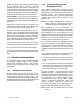
1.5.2 Status Indicator Panel for
Combined Interface/Load
Management Board
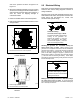
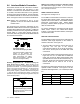
The LED Indicator panel includes the source available
and source connection LEDs that are included on the
standard indicator panel. The combined panel also
incudes load status LEDs and a Test button that cycles
the load management relays. See Figure 1-7. See
Section 3.4 for load management operation and test
information.
1
GM90763
1. Utility power available
2. Utility source supplying load
3. Generator source supplying load
4. Generator power available
5. Load add/shed relay status indicators
6. Load shed test button (cycles relays)
2
3
4
5
6
Figure 1-7 Optional Status Indicator Panel for
Combined Board