
RXT Transfer Switch Manual

TP-6807 1/1620 Section 2 Installation
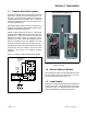
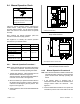
2.6 Interface Module Connection
The interface module must be connected to a Kohlerr
generator set equipped with the RDC2 or DC2
controller. Connect P10 on the interface module to the
A, B, PWR, and COM connections on the generator
set’s field-connection terminal block. See the generator
set Installation Manual for the location of the terminal
block. See Figure 2-8 for P10 connection identification.
Note: Engine start connections 3 and 4 on the
generator set are not used with the Model RXT
transfer switch.
This document gives connection information for one
Model RXT transfer switch connected to a generator set
equipped with an RDC2 or DC2 controller. If additional
accessory modules such as a programmable interface
module (PIM) or a load control module (LCM) are
connected, refer to the generator set installation manual
for connection instructions.
Accidental starting.
Can cause severe injury or death.
Disconnect the battery cables before
working on the generator set.
Remove the negative (--) lead first
when disconnecting the battery.
Reconnect the negative (--) lead last
when reconnecting the battery.
WARNING
Disabling the generator set. Accidental starting can
cause severe injury or death. Before working on the
generator set or equipment connected to the set, disable the
generator set as follows: (1) Press the generator set off/reset
button to shut down the generator set. (2) Disconnect the
power to the battery charger, if equipped. (3) Remove the
battery cables, negative (--) lead first. Reconnect the negative
(--) lead last when reconnecting the battery. Follow these
precautions to prevent the starting of the generator set by the
remote start/stop switch.
Hazardous voltage.
Will cause severe injury or death.
Disconnect all power sources before
opening the enclosure.
DANGER
Making line or auxiliary connections. Hazardous voltage
can cause severe injury or death. To prevent electrical
shock deenergize the normal power source before making any
line or auxiliary connections.
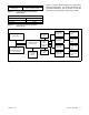
RBUS Connections A and B
See Figure 2-9 and Figure 2-10.
For the RBUS communication connections A and B to
the Model RXT transfer switch, optional PIM and/or
optional LCM or load shed kit, use 20 AWG shielded,
twisted-pair communication cable. Belden #9402
(two-pair) or Belden #8762 (single-pair) or equivalent
cable is recommended.
For outdoor installations, including those with buried
cables and/or conduit, use outdoor-rated Belden
#1075A or equivalent 20 AWG shielded, twisted-pair
communication cable.
PWR and COM Connections
For the PWR and COM connections, the cable size and
maximum cable length depends on the number of
modules connected. See Figure 2-9.
D For short cable runs shown in the first two rows of
Figure 2-9, use one pair in the two-pair
communication cable for the A and B connections,
and use the second pair for the PWR and COM
connections.
D For the longer cable runs shown in the last two rows of
Figure 2-9, use 12 or 14 AWG cable for PWR and
COM, and use the 20 AWG communication cable
specified above for the A and B connections only. In
this case, single-pair communication cable such as
Belden #8762 can be used for the A and B
connections.
The maximum cable length depends on the number of
optional modules connected. See Figure 2-9 for the
maximum cable lengths with 1, 2, or 3 modules per cable
run.
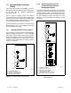
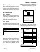
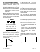
Connection Designation Description
P10-1 A Communication Line
P10-2 B Communication Line
P10-3 PWR 12 VDC
P10-4 COM 12 VDC
Figure 2-8 Controller Interface Connections