
RXT Transfer Switch Manual

TP-6807 1/1626 Section 2 Installation
2.8 Load Control Module (LCM)
Note: Only one load management option can be used
with the generator. If the LCM is connected to an
RXT equipped with the combined interface/load
management board, disable the load
management function on the combined board as
described in Section 2.8.2, below.
2.8.1 LCM with Standard Interface
Board
If the Load Control Module (LCM) is used with an RXT
transfer switch equipped with the standard interface
board, follow the instructions in TT-1574, provided with
the LCM, to connect the load control module and the
current transformer.
2.8.2 LCM with Co mbined Interface
Board
If the LCM is used with an RXT that is equipped with the
combined interface/load management board, disable
the load management function on the interface board as
described in the procedure below. Connect the LCM as
described in TT-1574. Be sure to connect the current
transformer to the LCM (not to the combined
interface/load management board on the RXT).
Note: The load status LEDs on the status indicator for
the combined interface/load management board
will not show the load control status of the LCM.
Accidental starting.
Can cause severe injury or death.
Disconnect the battery cables before
working on the generator set.
Remove the negative (--) lead first
when disconnecting the battery.
Reconnect the negative (--) lead last
when reconnecting the battery.
WARNING
Disabling the generator set. Accidental starting can
cause severe injury or death. Before working on the
generator set or equipment connected to the set, disable the
generator set as follows: (1) Press the generator set off/reset
button to shut down the generator set. (2) Disconnect the
power to the battery charger, if equipped. (3) Remove the
battery cables, negative (--) lead first. Reconnect the negative
(--) lead last when reconnecting the battery. Follow these
precautions to prevent the starting of the generator set by the
remote start/stop switch.
Hazardous voltage.
Will cause severe injury or death.
Disconnect all power sources before
opening the enclosure.
DANGER
Making line or auxiliary connections. Hazardous voltage
can cause severe injury or death. To prevent electrical
shock deenergize the normal power source before making any
line or auxiliary connections.
Procedure to connect an LCM if the combined
board is used on the RXT
1. Press the OFF button on the generator set
controller.
2. Disconnect the utility power to the generator set.
3. Disconnect the generator set engine starting
battery(ies), negative (--) lead first.
4. Disconnect power to the transfer switch.
5. Remove the ATS enclosure cover.
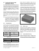
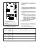
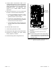
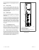
6. Find the combined interface/load management
board, which is typically mounted on the upper left
side of the enclosure. See Figure 2-16, if
necessary.
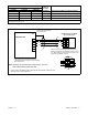
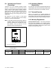
7. See Figure 2-20. Move the P11 jumper from
terminals 2 and 3 to terminals 1 and 2 to disable the
load management function on the combined board.