
RXT Transfer Switch Manual

TP-6807 1/16 29Section 3 Operation
Section 3 Operation
3.1 Model RXT Transfer Switch
Operation
The Model RXT transfer switch must be connected to a
generator set equipped with the RDC2 or DC2
controller. The RDC2/DC2 generator set/transfer
switch controller manages automatic transfer switch
(ATS) functions when connected to a Kohlerr Model
RXT transfer switch through the ATS interface board.
The controller receives voltage sensing data from the
Model RXT ATS and operates the generator set and
transfer switch to provide standby power when utility
power is lost.
See the generator set operation manual for:
D ATS status screens and configuration menus.
D Information about loaded exercise.
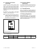
3.2 Source Availability
The Model RXT transfer switch supplies voltage
sensing data to the RDC2 or DC2 controller through the
ATS interface board. If the source voltage falls below
the undervoltage dropout setting, the source is
considered to have failed. See Figure 3-1.
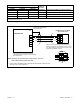
Voltage Sensing Parameter Setting
Accuracy ±5%
Undervoltage Dropout 90% of Pickup
Undervoltage Pickup 90% of Nominal
Figure 3-1 Voltage Sensing Parameters
3.3 ATS Control Sequence of
Operation
See Figure 3-10 for time delay settings.
Preferred Source Fails:
1. The load control contact opens.
2. The engine start time delay times out.
3. The generator set is signaled to start.
4. The generator starts and the emergency source
becomes available.
5. The normal-to-emergency time delay times out.
6. The transfer switch transfers to the emergency
source.
7. The load control contact time delay times out.
8. The load control contact closes.
Normal Source Returns:
1. The emergency-to-normal time delay times out.
2. The contactor transfers to the normal source.
3. The engine cooldown time delay times out.
4. The generator is signaled to stop.
3.4 Load Management Operation
The combined interface/load management board
provides load add and shed based on generator
capacity as described in this section.
Many appliances do not run continuously. Air
conditioners and furnaces, refrigerators, sump pumps,
and other appliances cycle on and off as needed. With
load management, less critical appliances can be
powered by the generator set when the more important
appliances are not running, allowing the use of a smaller
generator set than would be needed to run all of the
building’s electrical equipment at the same time.
The RDC2/DC2 generator controller receives input from
current transformer (provided with the combined
interface/load management board for installation in the
ATS) and determines whether to add or shed loads. The
combined interface/load management board receives
commands from the generator controller and energizes
or de-energizes the appropriate load relays.
The load management function is activated by the ATS
transferring from the utility (normal) source to the
generator. When activated, the load management
board sheds all connected loads. After transfer to the
generator set, loads are added according to their
priority.
If the ATS fails to transfer from the utility source to the
generator, the load management board will re-add all
loads. When the ATS transfers to utility, the load
management board adds all loads that have been
previously shed.