
RXT Transfer Switch Manual


TP-6807 1/16 15Section 2 Installation
Section 2 Installation
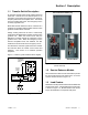
2.1 Introduction
Kohlerr transfer switches are shipped factory-wired,
factory-tested, and ready for installation. Have the
equipment installed only by trained and qualified
personnel, and verify that the installation complies with
applicable codes and standards. Protect the switch
against damage before and during installation.
2.2 Receipt of Unit
2.2.1 Insp ection
At the time of delivery, inspect the packaging and the
transfer switch for signs of shipping damage. Unpack
the transfer switch as soon as possible and inspect the
exterior and interior for shipping damage. If damage
and/or rough handling is evident, immediately file a
damage claim with the transportation company.
2.2.2 Storage
Store the transfer switch in its protective packing until
final installation. Protect the transfer switch at a ll times
from moisture, construction grit, and metal chips. Avoid
storage in cold or damp areas where moisture could
condense on the unit. See Figure 2-1 for acceptable
storage temperatures.
Item Specification
Storage
Temperature
-- 4 0 Cto85C(--40F to 185F)
Operating
Temperature
-- 2 0 Cto70C(--4F to 158F)
Humidity 5% to 95% noncondensing
Altitude 0 to 3050 m (10000 ft.) without derating
Figure 2-1 Environmental Specifications
2.2.3 Unpacking
Allow the equipment to warm to room temperature for at
least 24 hours before unpacking to prevent
condensation on the electrical apparatus. Use care
when unpacking to avoid damaging transfer switch
components. Use a vacuum cleaner or a dry cloth to
remove dirt and packing material that may have
accumulated in the transfer switch or any of its
components.
Note: Do not use compressed air to clean the switch.
Cleaning with compressed air can cause debris
to lodge in the components and damage the
switch.
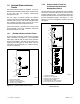
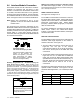
2.2.4 Lifting
Unbalanced weight.
Improper lifting can cause severe
injury or death and equipment
damage.
Use adequate lifting capacity.
Never leave the transfer switch
standing upright unless it is securely
bolted in place or stabilized.
WARNING
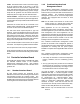
See Figure 2-2 or the dimensional drawing for the
weight of the transfer switch. Use a spreader bar to lift
the transfer switch. Attach the bar only to the
enclosure’s mounting holes or lifting brackets; do not lift
the unit any other way. Close and latch the enclosure
door before moving the unit.
Am
p
s Descri
p
tion
Weight ]
kg (lb.)
100
Single phase 7 (15)
With 12- or 16-space load center
(NEMA 1)
12 (26)
With 16-space load center 8 (18)
Three phase 14 (30)
Service entrance (ASE) 12 (26)
Service entrance (CSE) 16 (34)
150--200
Service entrance (ASE) 12 (26)
Service entrance (CSE) 16 (34)
200
Single phase 7 (15)
Three phase 14 (30)
300 Service entrance 46 (101)
400
Single phase 55 (120)
3-Pole/208--240 volts 41 (90)
3-Pole/480 volts 59 (130)
4-Pole 59 (130)
Service entrance 46 (101)
] Transfer switch weights are approximate and do not include
packaging.
Note: Enclosures are type NEMA 3R except as noted.
Figure 2-2 Weights (approximate)