
RXT Transfer Switch Manual


TP-6807 1/1616 Section 2 Installation
2.3 Installation
NOTICE
Foreign material contamination. Cover the transfer switch
during installation to keep dirt, grit, metal drill chips, and other
debris out of the components. Cover the solenoid mechanism
during installation. After installation, use the manual operating
handle to cycle the contactor to verify that it operates freely.
Do not use a screwdriver to force the contactor mechanism.
The transfer switch may use both American Standard and
metric hardware. Use the correct size tools to prevent
rounding of the bolt heads and nuts.
Check the system voltage and frequency. Compare
the voltage and frequency shown on the transfer switch
nameplate to the source voltage and frequency. Do not
install the transfer switch if the voltage and frequency
are different from the normal (utility) source voltage and
frequency or the emergency source voltage and
frequency shown on the generator set nameplate.
Plan the installation. Use the dimensions given on the
enclosure dimension (ADV) drawings in Section 6.
Select a mounting site that complies with local electrical
code restrictions for the enclosure type. Mount the
transfer switch as close to the load and power sources
as possible. Allow adequate space to open the
enclosure and service the switch.
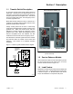
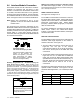
NEMA 3R enclosures. To remove the enclosure’s front
panel, support the panel while removing the screws.
Pull the bottom of the panel out and down until the top
clears the enclosure. Remove the inner panel to access
the transfer switch components.
NEMA 3R enclosures have locking tabs at the bottom of
the enclosure and the door. Use a padlock to lock the
door after installation is complete.
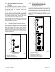
Wall mounting. Mount the transfer switch to a wall or
other rigid vertical supporting structure. Refer to the
dimension drawings in Section 6 for hole locations. Use
shims to plumb the enclosure.
Cover the transfer switch’s internal components to
protect them from drill chips or debris during installation.
Use a vacuum cleaner to remove debris from the
enclosure.
Note: Do not use compressed air to clean the switch.
Cleaning with compressed air can cause debris
to lodge in the components and cause damage.
Clearance holes through the back of each enclosure are
provided for mounting. The mounting holes on NEMA
3R enclosures have gaskets to seal out moisture. Use
washers with the mounting screws to protect the
gaskets.