
RXT Transfer Switch Manual


TP-6807 1/16 17Section 2 Installation
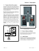
2.4 Manual Operation Check
Hazardous voltage.
Will cause severe injury or death.
Disconnect all power sources before
opening the enclosure.
DANGER
Check the manual operation before energizing the
transfer switch. Verify that the contactor operates
smoothly without binding. Do not place the transfer
switch into service if the contactor does not operate
smoothly.
After checking the manual operation, place the
contactor in the Normal (utility) position.
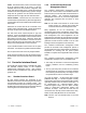
See Figure 2-3 to identify the manual operation
procedure for your transfer switch.
ATS Procedure Figure
100--200 amps, 1-phase 2.4.1 Figure 2-4
100--200 amps, 3-phase 2.4.2 Figure 2-6
300 amps, 1-phase
2.4.1 Figure 2-5
400 amps, 1-phase
400 amps, 3-phase, 3-pole,
208--240 Volts
400 amps, 3-phase,
3-pole/480 Volt and 4-pole
2.4.2 Figure 2-7
Figure 2-3 Manual Operation Procedure Guide
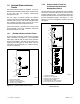
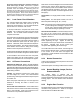
2.4.1 Manual Operation Procedure 1
Note: Never manually operate the transfer switch when
the power is connected. Disconnect both power
sources before manually operating the switch.
1. 100-200 amp switches: These switches have an
attached handle as shown in Figure 2-4.
400 amp switches: Slide the detachable handle or
a wrench over the shaft. See Figure 2-5.
2. Move the handle up to place the transfer switch in
the Normal Source position or down to place the
contactor in the Emergency Source position. See
Figure 2-4 or Figure 2-5.
3. 400 amp switches: Remove the detachable handle
or wrench.
4
3
7
8
CN
CE
NL1
NL2
EL2EL1
SCN
C
NO
NC
SCE
C
NC
NO
1
1. Handle (not detachable)
Figure 2-4 Manual Operation, 100 -- 200 Amp
Single-Phase Switches
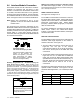
1
GM80139
1. Shaft (attach handle or wrench here)
Figure 2-5 Manual Operation, 300--400 Amp Single-
Phase and 208--240 Volt Switches
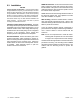
2.4.2 Manual Operation Procedure 2
Note: Never use the maintenance handle to transfer the
load with the power connected. Disconnect both
power sources before manually operating the
switch.
1. If the transfer switch is equipped with a
maintenance handle, remove the handle from its
storage location inside the enclosure. See
Figure 2-7.
2. Insert the maintenance handle or a tool (such as a
screwdriver) into the hole in the shaft on the left