
RXT Transfer Switch Manual


TP-6807 1/16 19Section 2 Installation
Grounding electrical equipment. Hazardous voltage can
cause severe injury or death. Electrocution is possible
whenever electricity is present. Ensure you comply with all
applicable codes and standards. Electrically ground the
generator set and related equipment and electrical circuits.
Turn off the main circuit breakers of all power sources before
servicing the equipment. Never contact electrical leads or
appliances when standing in water or on wet ground because
these conditions increase the risk of electrocution.
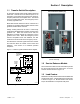
2.5.1 L oad Center Circuit Breakers
The 100 amp Model RXT transfer switch is available
with a built-in load center with room for up to 16
single-pole circuit breakers. Up to 8 tandem breakers
can be used for a maximum of 24 circuits.
A 100 amp model with a 12-space load center is also
available. The 12-space load center uses only single
breakers. Do not install tandem breakers on the
12-space load center.
The load centers use Square D type QO or QOT tandem
breakers. In an essential load application, the breakers
can be moved from the main panel to the load center if
the main distribution panel uses the same type of
breakers. Otherwise, obtain and install new Square D
type QO circuit breakers. The rating of the load center
circuit breaker must match the rating of the existing
breaker in the main panel for each circuit.
Verify that the total rating for all breakers used in the load
center does not exceed the rating of the transfer switch.
If circuit breakers are removed from the load panel,
install cover plates over the vacant positions. Cover
plates can be obtained from a local Square D supplier.
2.5.2 AC Power Conn ections
Determine the cable size. Refer to the ADV drawings
in Section 6 or the transfer switch specification sheet to
determine the cable size required for the transfer switch.
Make sure the lugs provided are suitable for use with the
cables being installed.
Conduit. Use separate conduit for AC power wiring
and low-voltage DC, control, and communication
system wiri n g . Watertight conduit hubs may be required
for outdoor use.
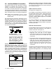
Select the proper cable clamp or use other approved
methods for securing the cable or conduit to the
enclosure.
Source and load connections. Clean cables with a
wire brush to remove surface oxides before connecting
them to the terminals. Apply joint compound to the
connections of any aluminum conductors.
Refer to the connection diagrams on the transfer switch
enclosure door and the wiring diagrams in Section 6.
The connection points on the transfer switch contactor
are labelled Normal, Emergency, and Load. Connect
the utility power to Normal. Connect the generator set to
Emergency.
Single phase. For single-phase models, connect to A
and C.
Three phase. For three-phase models, be sure to
follow the phase markings (A, B, C, and N).
Note: Connect the source and load phases as indicated
by the markings and drawings to prevent short
circuits and to prevent phase-sensitive devices
from malfunctioning or operating in reverse.
Service entrance models. Connect the utility source to
the lugs on the normal source disconnect circuit
breakers as shown in the service entrance switch wiring
diagram in Section 6.
Verify that all connections are consistent with drawings
before tightening the lugs. Tighten all cable lug
connections to the torque values shown on the label on
the switch. Carefully wipe off any excess joint
compound after tightening the terminal lugs.
On models with built-in load centers, the load lugs are
factory-wired to the load center. Connect the load leads
to the circuits in the load center and tighten the
connections. Check the labels on the breakers for the
tightening torques.
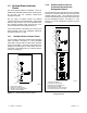
2.5.3 Neutral Connection
Connect the neutral from the main panel to the neutral
lug in the ATS enclosure.
Ground the system according to NEC and local codes.
2.5.4 Neutral Bonding Jumper, Service
Entrance Models
The transfer switch is shipped with the
neutral-to-ground jumper installed. For non-service
entrance applications, disconnect the neutral-to-ground
bonding jumper. See the transfer switch dimension
drawing.
2.5.5 Engine Start Function
The engine start function is controlled by the RDC2/DC2
controller on the generator set. There are no engine
start terminals on the Model RXT ATS.