
RXT Transfer Switch Manual


TP-6807 1/16 21Section 2 Installation
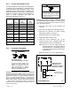
Maximum cable length per run, meters (ft.)
Indoor or
Outdoor
Installation
Cable Size for PWR and COM Connections
Number of Modules per Run
1 Module 2 Modules 3 Modules
61 (200) 31 (100) 21 (67)
Indoor 20 AWG Belden #9402 or equivalent, two-pair
61 (200) 31 (100) 21 (67)
Outdoor 20 AWG Belden #1075A or equivalent, two-pair
152 (500) 152 (500) 122 (400)
— 14 AWG *
152 (500) 152 (500) 152 (500)
— 12 AWG *
* Use 12 or 14 AWG cable for PWR and COM connections only. For RBUS connections A and B, use shielded, twisted pair communication
cable specified in Section 2.6.
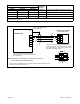
Figure 2-9 Cable Specifications for PWR and COM Connections
1. Communication cable Belden #9402 or equivalent 20 AWG shielded, twisted-pair cable.
See Figure 2-9 for cable specifications.
Interface Board on the Model
RXT Transfer Switch
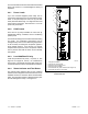
Note: Generator set terminal block connections 3 and 4 are
NOT USED with the Model RXT ATS.
RXT
Leave one end of each cable shield disconnected.
If accessory modules are connected in series, connect
the c able shields as shown below and refer to the
generator set installation manual.
Generator Set
COM
PWR
B
A
Connect one end of each
cable shield to GROUND at
the generator set.
RXT
COM
PWR
B
A
1
GND
Generator Set Terminal Block.
See the generator set manuals for location.
Check the decal on the generator set for terminal
block connections.
A
B
COM
PWR
3
4
Figure 2-10 Interface Module Connection to Generator Set Field-Connection Terminal Block