
RXT Transfer Switch Manual


TP-6807 1/1622 Section 2 Installation
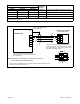
2.7 Combined Interface/Load
Management Board
The combined interface/ load management board can
be used with single-phase generator sets equipped with
the RDC2 or DC2 controller only. Follow the instructions
in this section to install the current transformer and
connect the load management relays. Then connect the
interface/load management board to a Kohlerr
generator set equipped with the RDC2 or DC2
controller.
Up to four load relays and two HVAC relays can be
connected. The load management operation will cycle
through all six connections regardless of the number of
loads connected. The load management timing is
affected by the generator’s capacity as described in
Section 3.5.
Note: Only one load management option can be used
with the generator. If a load control module (LCM)
is connected, disable the load management
function on the combined interface/load
management board as described in Section 2.8
and connect the LCM according to instruction
sheet TT-1574, provided with the LCM.
2.7.1 Relay Modules
Up to four power relay modules (GM92001-KP1-QS)
can be connected for management of non-essential
secondary loads. Two (2) 120 VAC loads (shed
simultaneously) or a single 240 VAC load can be wired
to each relay. Customer-supplied relays must be either
normally closed or double-pole double-trhow (DPDT)
and maximum 50 amps. Note that the load must be
connected to the normally closed contacts of the relay.
Kohlerr Power Relay Modules are recommended.
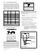
Circuit Board
Relays
Rating
Pilot Relays and
HVAC Relays
(qty. 2)
125VAC, 10 A (general purpose)
120VAC, 125VA (pilot duty)
Figure 2-11 Combined Interface Board Relay
Specifications
Power Relay Specifications
Relay Rating 50 A @ 240 VAC
Relay Type DPST -- NC or DPDT
Coil Voltage 120 VAC
Figure 2-12 Customer-Supplied Power Relay
Specifications
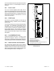
Kohlerr power relay modules include one power relay
mounted inside a NEMA type 3R enclosure. Connect up
to four (4) power relay modules to the load shed kit. See
Figure 2-13 for an illustration of a power relay module.
Before starting the installation, confirm that the
generator set is equipped with an RDC2 or DC2
controller. RDC2/DC2 controller firmware version 5.04
or higher is required. Check the version number on the
controller and update the firmware, if necessary.
An adequate electrical supply is required for operation
of the customer-supplied relays connected to the load
shed kit. 120 VAC relays require a customer-supplied
voltage source. Check the electrical requirements of the
customer-provided equipment prior to installation to
determine the wire size and circuit protection required.
Verify that customer-provided equipment complies with
applicable local and national electrical codes.
Figure 2-13 Kohler Power Relay Module
2.7.2 HVAC Loads
There are two (2) relays available to control two (2)
independent heating, ventilation, and air conditioning
(HVAC) loads. The operation of the HVAC relays
includes a five-minute start delay and different timing for
load add compared to the power relays. See
Section 3.5.1 for more details about the HVAC relay
operation.
2.7.3 Load Add/Shed Priority
Loads are prioritized from priority 1 to priority 6. See
Figure 2-19 on page 25. Priority 1 is considered the
most critical; it will add first and shed last. Priority 6 is
considered the least critical; it will add last and shed first.